
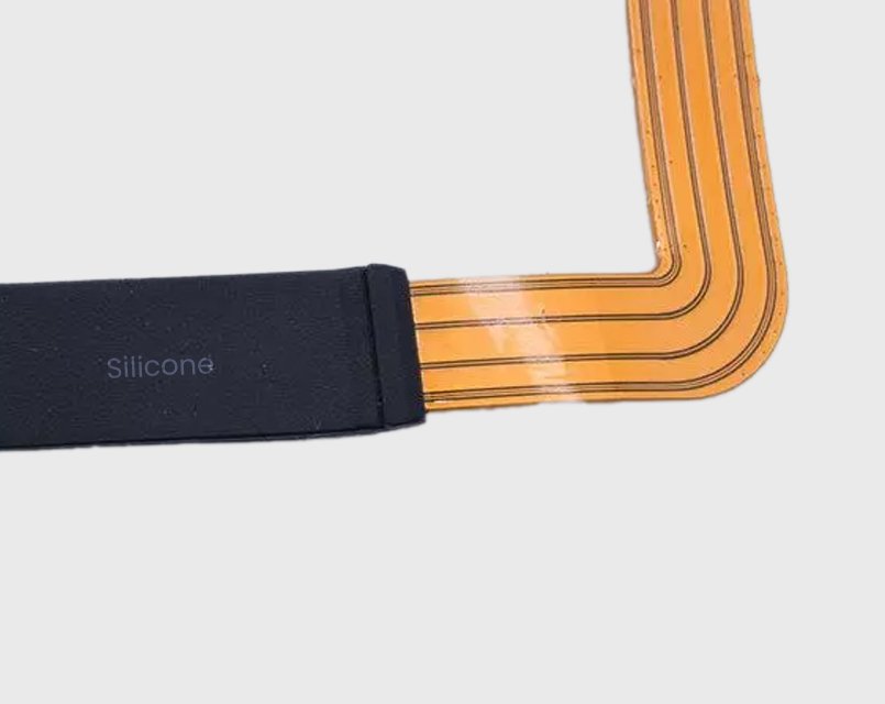
Flexible printed circuits are widely used where rigid PCBs and wire harnesses cannot provide enough flexibility or routing freedom. They appear in wearable electronics, medical sensors, automotive lighting, camera modules, robotic joints, foldable devices, and many other compact electronic assemblies.
The same thin structure that makes an FPC useful also makes it vulnerable. Repeated bending can concentrate stress around copper traces and solder joints. Moisture may enter through connector areas or exposed circuit regions. Vibration can fatigue component joints, while pulling force on cables can damage conductor transitions.
LSR overmolding provides a way to integrate mechanical protection, sealing, strain relief, electrical insulation, and environmental protection directly around the FPC.
Unlike applying silicone adhesive or dispensing potting material onto the circuit, LSR overmolding places the FPC inside a precision mold and injects liquid silicone rubber around selected areas or around the full circuit. The silicone cures inside the mold to create a repeatable three-dimensional protective structure.
The most important process question is often temperature. Silicone rubber is molded through heat curing and crosslinking, while an FPC is built from heat-sensitive layers such as polyimide film, copper traces, coverlay adhesive, solder mask, connector plastics, solder joints, and sometimes mounted components. A practical FPC overmolding plan must confirm that the circuit stack-up can tolerate the molding temperature and exposure time before tooling moves forward.
Why Overmold an FPC with Liquid Silicone Rubber?
An unprotected FPC is usually designed primarily for electrical interconnection. Its copper traces, polyimide substrate, coverlay, component interfaces, and connector termination areas can all become failure points when exposed to movement, moisture, vibration, or pulling force.
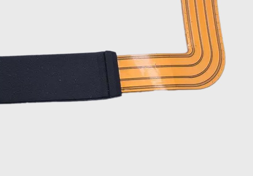
LSR overmolding adds a compliant protective layer around these structures. The cured silicone absorbs part of the mechanical load generated by vibration, impact, pulling, and repeated bending. Around connector exits and solder transitions, silicone can act as an integrated strain-relief structure, reducing abrupt deformation between rigid and flexible regions.
Silicone also provides good resistance to moisture, temperature cycling, UV exposure, and many environmental contaminants. This makes the process useful for electronics that must operate outdoors, inside vehicles, close to the human body, or in equipment exposed to frequent motion.
When the FPC, connector transitions, interfaces, and surrounding housing are designed together, silicone encapsulation can contribute to IP67- or IP68-level sealing. The final IP rating should still be verified on the complete assembly, not assumed from the silicone material alone.
Full FPC Encapsulation vs. Selective Overmolding
There are two common ways to overmold an FPC.
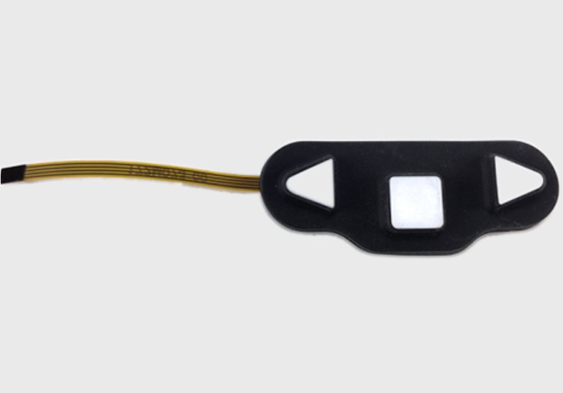
Full encapsulation places most or all of the FPC conductor area, coverlay, and selected connector roots inside a continuous silicone body. This creates a 360-degree protective layer around the flexible circuit. Full encapsulation is useful when water resistance, contamination protection, impact protection, electrical insulation, and mechanical reinforcement are priorities. Typical examples include wearable electronics, medical probes, sensor cables, automotive lighting modules, and environmental sensing systems.
Selective overmolding is different. Silicone is molded only around areas that require reinforcement, such as bending zones, component pads, solder joints, connector roots, or transitions between rigid and flexible sections. This keeps the remaining FPC thin and flexible. Selective overmolding is often better for dynamic-flex applications because full encapsulation can increase bending stiffness. Protecting only high-stress regions allows designers to keep the original bending radius in other areas while reinforcing the points most likely to fail.
The choice should be based on the actual deformation mode of the FPC, not simply on maximizing silicone coverage.
Process and Tooling
FPC and Overmolding Structure Design
A reliable process begins before the mold is built.
The FPC drawing should define which areas must remain exposed, which areas require silicone coverage, where connectors enter and exit the overmold, and which sections must continue bending during use.
Transitions between overmolded and non-overmolded regions need special attention. If the silicone ends abruptly at a dynamic bending zone, the overmold edge can become a new stress concentration point.
A gradual transition, rounded silicone geometry, and sufficient distance between the silicone edge and the highest-strain bending region can improve fatigue life.
Silicone thickness must balance protection and flexibility. Very thin layers provide less reinforcement and are more sensitive to filling variation. Excessively thick layers add stiffness, weight, material usage, and cure time.
For many compact FPC structures, approximately 0.3-3.0 mm is a practical design range. The final value should be determined by circuit geometry, application load, injection behavior, and insulation or sealing requirements.
FPC Positioning Inside the Mold
A flexible circuit does not behave like a rigid metal or plastic insert. It can bend, wrinkle, float, twist, or shift when the mold closes or when liquid silicone enters the cavity.
The mold therefore needs dedicated locating features. Depending on the FPC geometry, positioning may use locating holes, precision pins, mechanical nests, vacuum holding, clamping areas, or a combination of these methods.
The goal is not only to hold the FPC before injection. The positioning structure must prevent movement through mold closing, injection, and curing without damaging copper traces or creating excessive compression marks.
For precision FPC overmolding, critical positioning regions may require very tight tooling control. This is especially important when exposed contact pads, connectors, or narrow sealing boundaries must remain free of silicone.
Mold Design for LSR Flow
Once the FPC is fixed inside the cavity, the next challenge is controlling silicone flow.
LSR has low viscosity before curing. This allows it to fill thin sections and complex geometries, but it also means the material can enter very small gaps.
Poor parting-line control can cause flash. More seriously, silicone may flow into connector contacts, electrical interfaces, or other areas that must remain exposed.
Gate location should be designed so the initial flow front does not directly hit a thin unsupported section of FPC. High local flow force can move or fold the circuit before the cavity is filled.
For complicated FPC geometries, mold-flow review and prototype tooling can help evaluate flow direction, air traps, pressure distribution, weld lines, and filling balance.
Venting is equally important. Air trapped around FPC edges, cavities, components, or through-holes can cause short shots, bubbles, incomplete coverage, or weak sealing areas. Because the FPC divides the cavity into multiple flow paths, venting is often more complex than in a conventional silicone part.
Surface and Silicone-to-FPC Adhesion
Mechanical encapsulation does not automatically mean strong adhesion.
An FPC may contain polyimide film, coverlay adhesive, copper, solder mask, connector plastics, electronic components, and different surface treatments. Each surface can behave differently with silicone.
Depending on the material combination, bonding may rely on chemical adhesion, surface treatment, primer systems, or mechanical anchoring created by the molded geometry. Because silicone does not always form a strong chemical bond to every FPC surface, the circuit should also include mechanical lock features where possible. Through holes, slots, notches, edge openings, or local anchor windows can let silicone flow through or around the FPC and create a more reliable mechanical interlock.
Before production, the actual FPC stack-up should be tested with the selected LSR grade. Release agents, oils, flux residues, fingerprints, moisture, and processing contaminants can all reduce bonding strength.
Plasma cleaning is commonly used before FPC silicone overmolding because it removes fine contamination and activates the surface before bonding. For many FPC stack-ups, plasma treatment should be treated as a required validation step rather than an optional cosmetic cleaning process.
Primer can also be critical. After plasma cleaning, a dedicated silicone bonding primer may be applied to the overmold area to improve adhesion between the cured silicone and the FPC surface. Primer selection, coating thickness, drying condition, open time, and cleanliness all need process control. The bonding method should be validated with real production materials rather than relying only on published material compatibility data.
LSR Molding and Curing
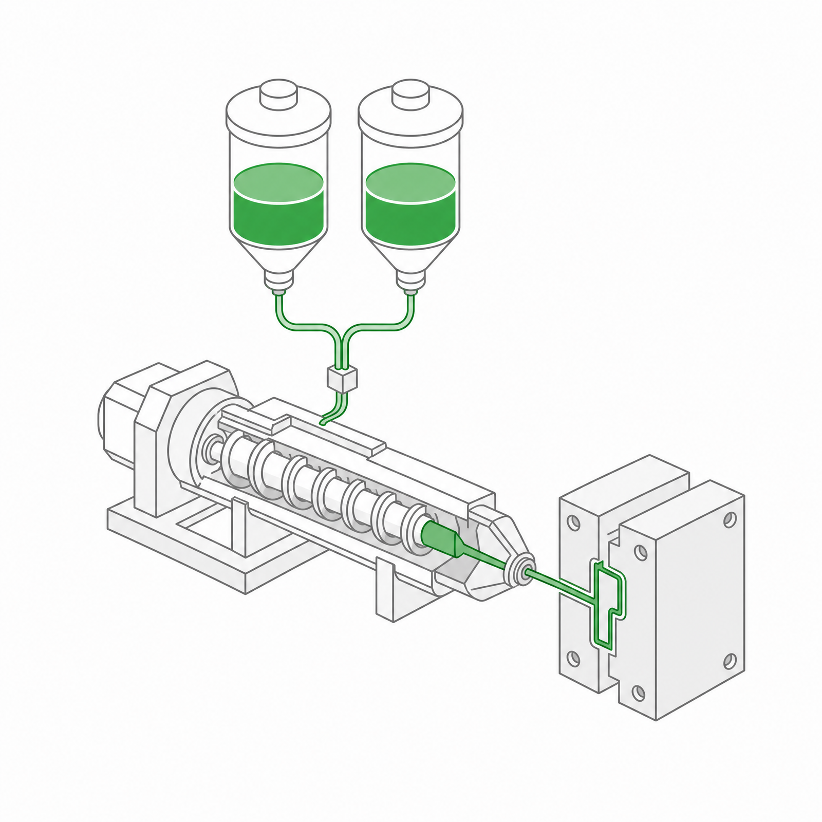
After the FPC is loaded and the mold closes, two-component liquid silicone rubber is metered, mixed, and injected into the heated mold.
Process conditions must be selected carefully because the circuit is already inside the cavity. Temperature is the first condition to review, because silicone rubber needs heat to vulcanize and crosslink while the FPC may contain adhesives, connector bodies, solder joints, and components with lower heat tolerance than the silicone itself.
Injection pressure should be enough to fill the silicone geometry, but not so aggressive that it displaces the FPC or damages components. Gate size, injection speed, cavity volume, silicone viscosity, and venting all influence the required filling pressure.
Mold temperature, cure time, and actual heat soak should remain compatible with the FPC materials and any mounted electronic components. The review should include the FPC laminate, coverlay adhesive, stiffener adhesive, solder mask, connector plastics, surface finishes, solder joints, sensors, and any pressure-sensitive or heat-sensitive parts.
Silicone typically cures at elevated mold temperatures, but actual temperature and cure time depend on the LSR formulation, part thickness, component sensitivity, and production cycle requirements. If the FPC stack-up cannot tolerate the required cure window, the project may need a different silicone grade, lower-temperature process window, shorter heat exposure, different insert design, or a change in FPC material selection.
The FPC should be treated as an electronic insert, not simply as another molded substrate.
LSR Material Selection Examples for FPC Overmolding
Material selection should start from the application, not only from hardness. The examples below can be used for early discussion, but final selection should be checked against the supplier datasheet, FPC stack-up, molding temperature window, bonding method, regulatory requirements, and prototype test results.
| Applications | Material options | Properties |
|---|---|---|
| Transparent window for wearable devices | Optical or high-transparency LSR, such as Dow SE 1700 type materials | Light transmission, haze, Shore A 20-30 range, yellowing, skin contact, and bonding to the FPC or housing |
| Medical skin-contact assemblies | Medical-grade LSR, such as Wacker LR 5040 type materials | Biocompatibility documentation, USP Class VI or ISO 10993 needs, Shore A 30-40 range, clean molding, and extractables review |
| Automotive high-temperature areas | Heat-resistant LSR, such as Momentive 7-4050 type materials | Long-term temperature exposure, compression set, vibration, connector plastics, and aging after heat cycling |
| High-frequency signal protection | Low-dielectric LSR, such as Momentive 7-4030 type materials | Dielectric constant, signal loss, shielding layout, silicone thickness, and influence on antenna or high-speed traces |
| General FPC protection | General-purpose fast-curing LSR, such as Wacker LR 3003/20 type materials | Adjustable hardness, lower-temperature process window, adhesion method, strain relief, and sealing performance |
Demolding and Post Molding
After curing, the overmolded circuit is removed from the mold. Demolding force must be controlled because pulling the silicone structure too aggressively can introduce stress into the FPC or connector termination.
Inspection should focus on both the molded silicone and the embedded circuit.
Important characteristics include silicone coverage, flash, exposed electrical contact areas, FPC location, edge sealing, voids, incomplete filling, surface defects, connector contamination, and visible deformation of the circuit.
For critical projects, dimensional inspection can be combined with electrical continuity testing, functional testing, bending tests, pull tests, sealing tests, and environmental aging tests.
Common Problems in FPC Silicone Overmolding
FPC movement is one of the most frequent process risks. If the circuit shifts during injection, silicone thickness becomes inconsistent and exposed electrical areas may become partially covered. Improving locating features, vacuum holding, cavity support, or injection direction is usually better than only reducing injection speed.
Heat damage is another central risk. Excessive mold temperature or cure time can soften adhesives, deform connector plastics, stress solder joints, discolor materials, or change the mechanical behavior of the FPC after molding. Early thermal validation helps avoid a part that looks acceptable after molding but fails after bending, pull testing, or aging.
Flash is another important issue because uncured LSR can enter extremely small mold gaps. High-precision shut-off surfaces are especially important around connectors, exposed pads, and thin FPC edges.
Delamination between silicone and the FPC usually indicates that material compatibility or surface preparation has not been fully controlled. Contamination, insufficient surface activation, unsuitable silicone chemistry, or excessive mechanical stress can all contribute.
Air entrapment may appear as internal bubbles or incomplete silicone coverage. It often occurs around component edges, holes, narrow cavities, and transitions where the FPC blocks the natural air escape path.
Excessive stiffness can become a design failure even if the molding process itself is successful. If a dynamic FPC is encapsulated with too much silicone, bending stress may move to the edge of the overmold. This is why dynamic-flex designs often benefit from selective overmolding.
Applications of LSR Overmolded FPCs
LSR overmolding is useful where electrical interconnection must coexist with movement, moisture, vibration, or limited installation space.
Wearable devices such as smart watches, fitness trackers, hearables, and compact sensors can use silicone-overmolded FPCs to combine sealing, comfort, and flexible electrical routing.
Medical probes and sensor assemblies benefit from integrated strain relief and protection around sensitive electrical connections. For patient-contact products, the selected silicone system must meet the required biocompatibility and regulatory requirements for the intended use.
Automotive applications include lighting modules, mirror systems, sensors, interior electronics, and other assemblies exposed to vibration, temperature cycling, and moisture.
Industrial robots and moving equipment can use selective overmolding around high-stress FPC sections inside joints and compact moving modules. Similar designs can also be used in foldable consumer electronics, where maintaining flexibility outside the protected region is especially important.
Conclusion
LSR overmolding for flexible printed circuits should be treated as an integrated mechanical, electrical, material, and tooling project.
A well designed FPC overmolding process does more than cover the circuit with silicone. It controls where the circuit bends, where stress is transferred, how moisture is blocked, how connectors are reinforced, and how the complete assembly behaves over thousands or millions of cycles. That is where LSR overmolding becomes a functional engineering solution rather than a secondary coating process.
 LSR Injection Molding
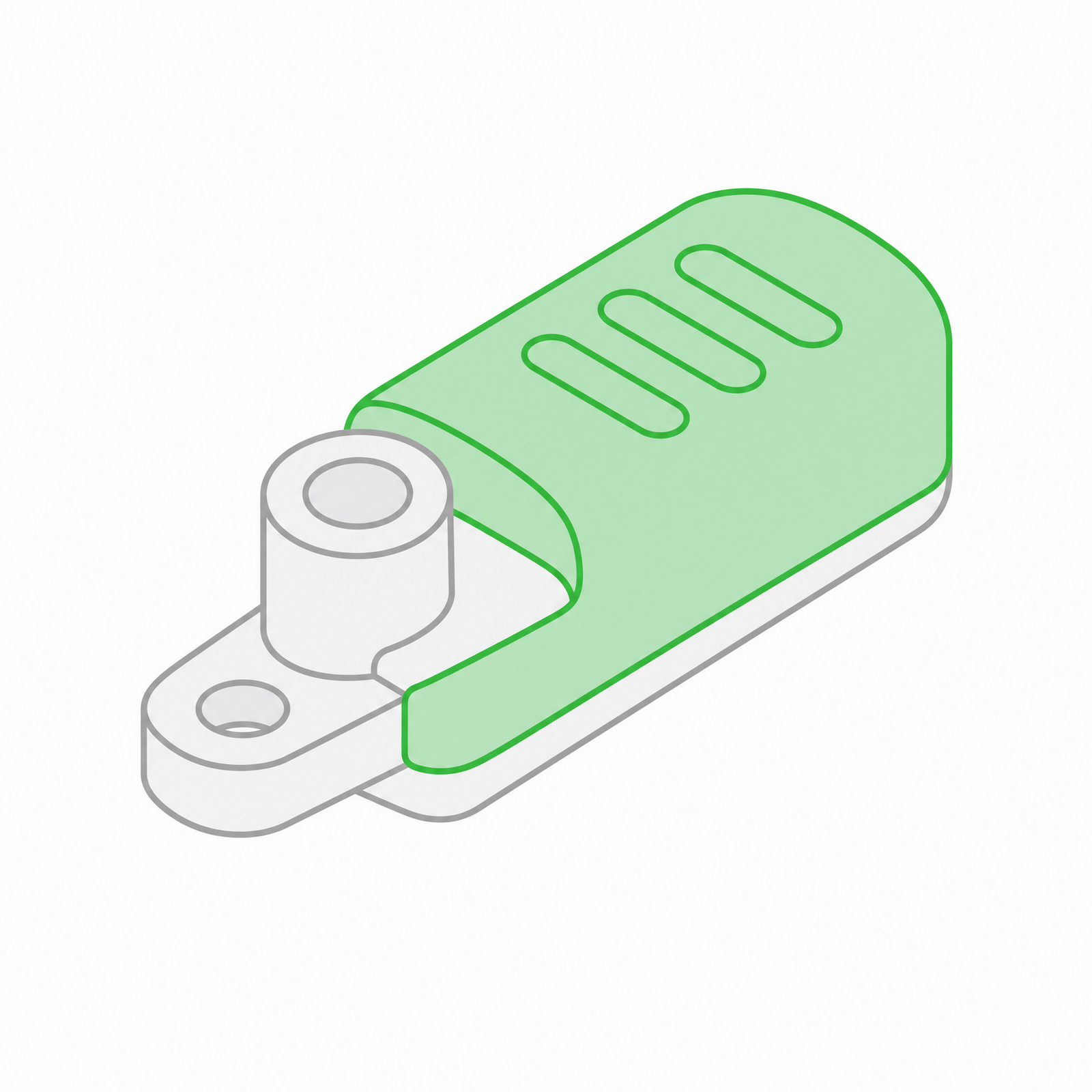 Silicone Rubber Overmolding
 Compression Molding
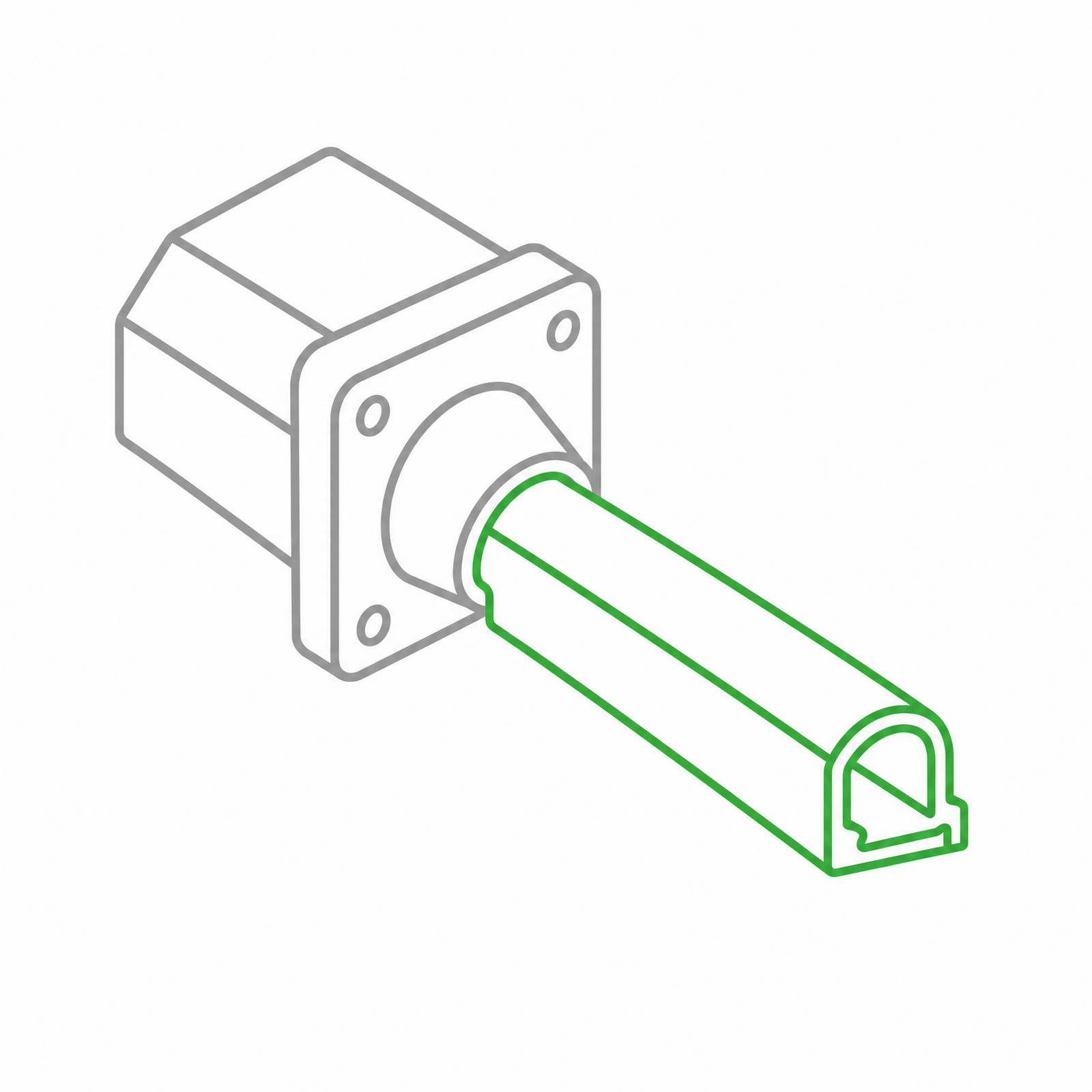 Silicone Rubber Extrusion
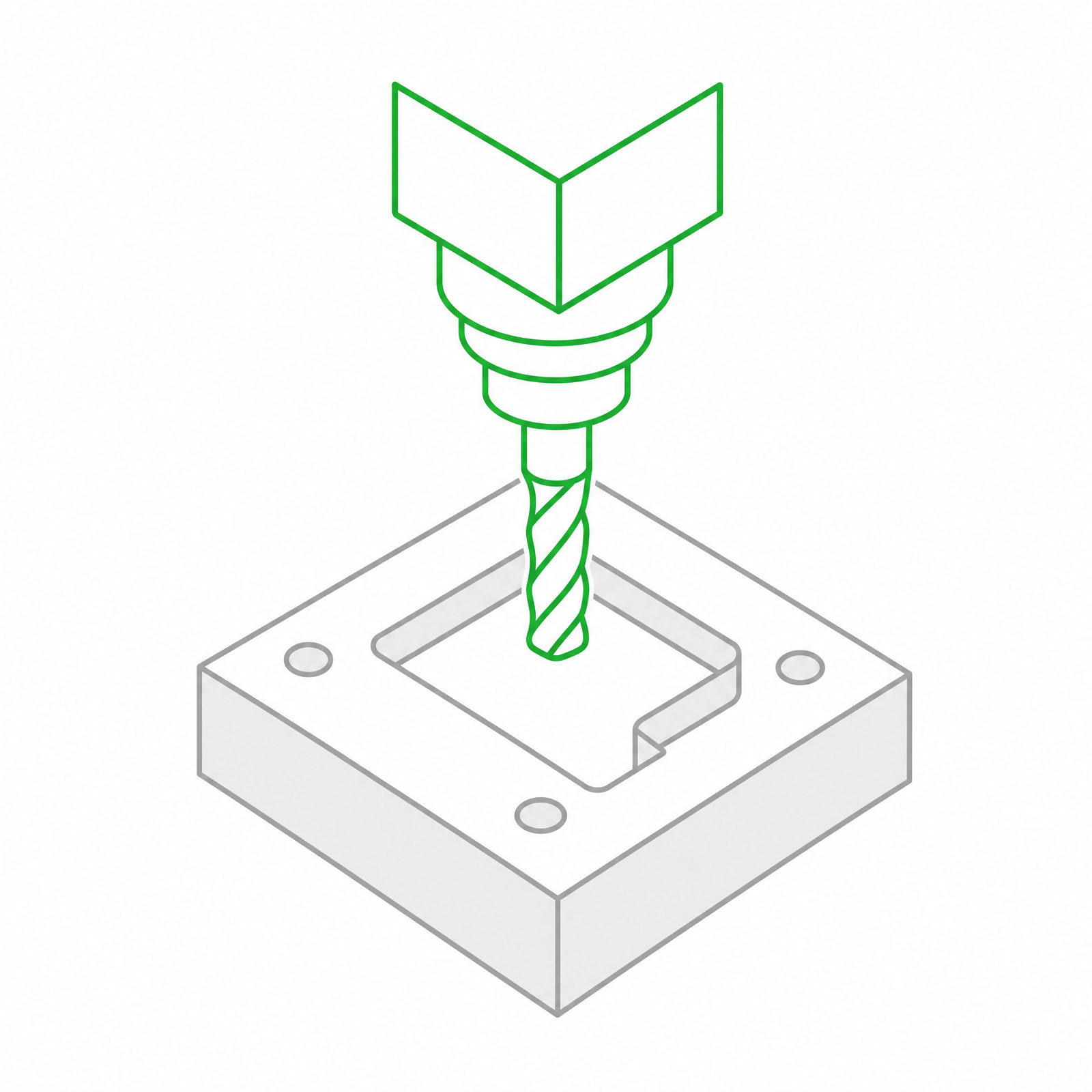 In-house Tooling