
Conductive Silicone Rubber
Conductive silicone contains fillers such as carbon black, silver powder, or copper powder. These fillers give the material electrical conductivity. Conductive layers are usually black or gray.
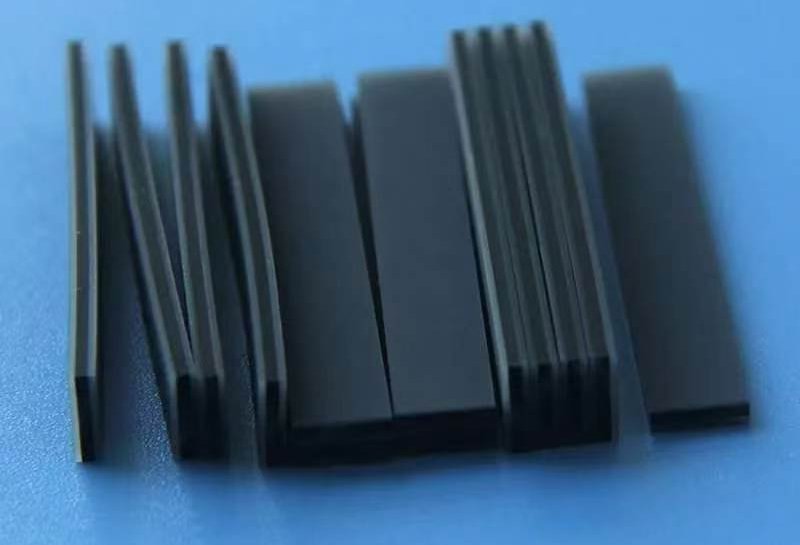
Conductive silicone rubber zebra strips for stable LCD-to-PCB signal connection in compact electronic assemblies.
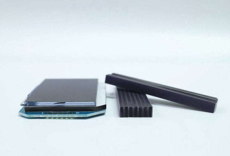
A silicone rubber zebra connector, also called a zebra strip or conductive rubber strip, is an elastomeric connector made by stacking alternating layers of conductive silicone and insulating silicone, then vulcanizing them into a single flexible strip.
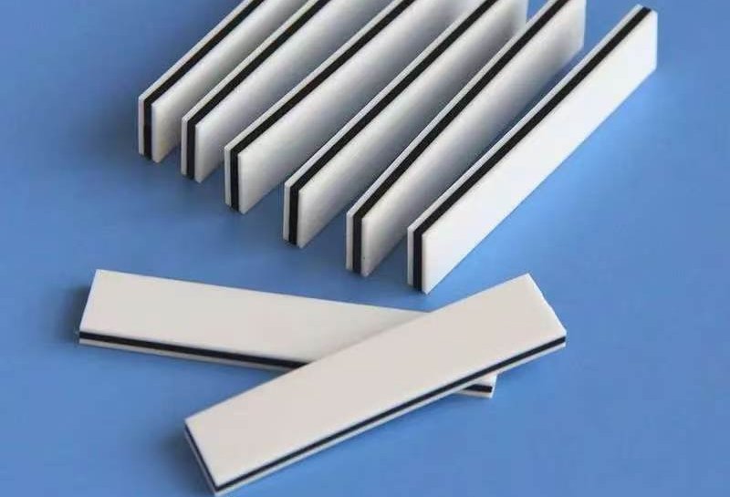
Its cross-section shows a black-and-white striped pattern, which is why it is commonly called a zebra strip. The connector uses the elasticity and conductivity of silicone rubber to create an electrical connection between an LCD and a PCB.
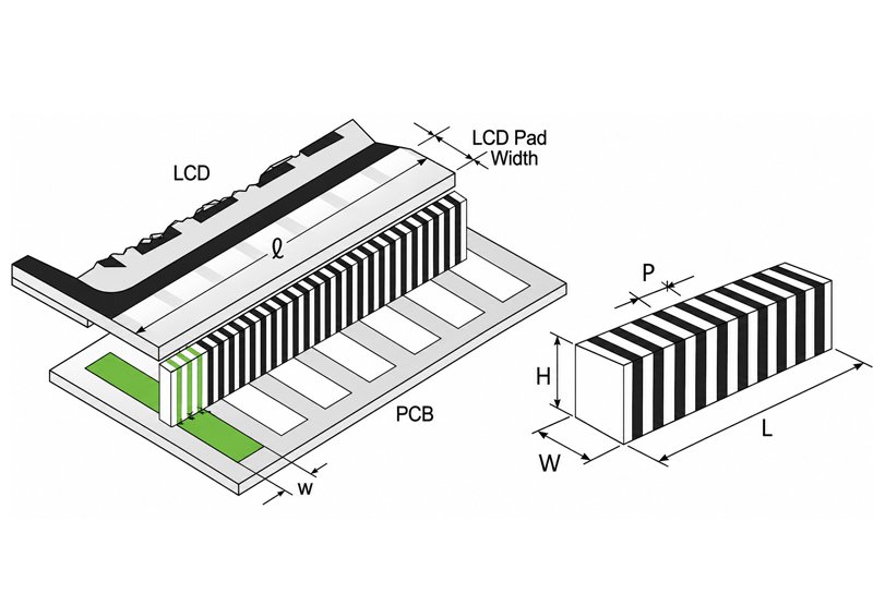
A zebra connector is mainly made from two silicone materials: conductive silicone and insulating silicone. The layered structure gives the strip one key feature: it conducts vertically but insulates laterally.
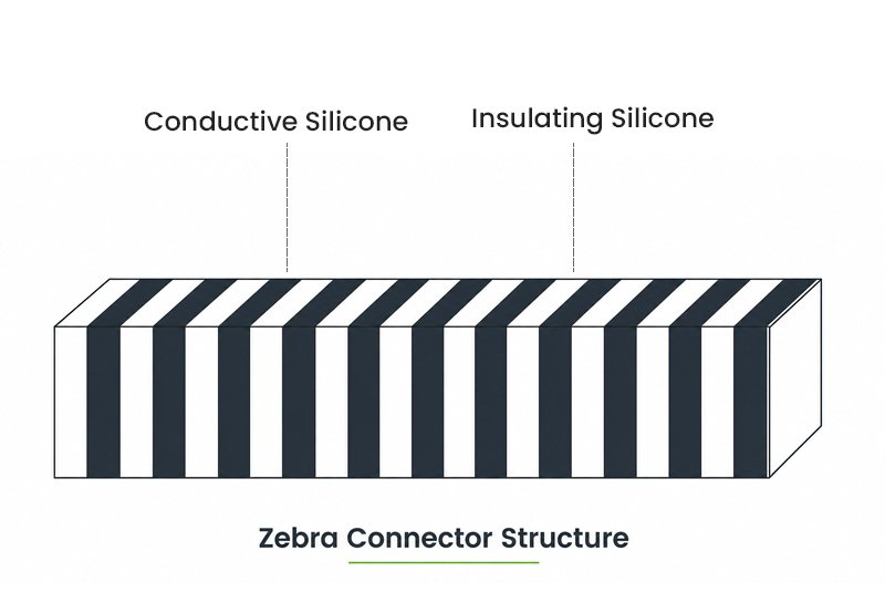
Conductive silicone contains fillers such as carbon black, silver powder, or copper powder. These fillers give the material electrical conductivity. Conductive layers are usually black or gray.
Insulating silicone works as the isolation layer between conductive paths. It prevents short circuits between adjacent electrodes and provides good elasticity and insulation.
Choose the connector structure to fit the display stack and provide the required compression. Insulating supports can help locate the strip within the housing. YY-type, YE-type, and custom profiles are also available.
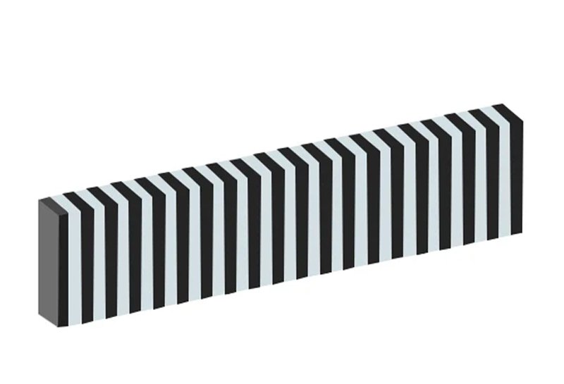
The most common type. It is made from alternating conductive and insulating silicone layers and has a clear zebra-like stripe pattern.
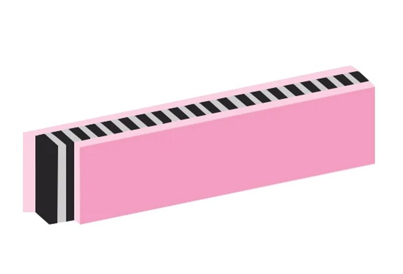
A soft sponge-like silicone layer is added to one or both sides for insulation, cushioning, and vibration absorption.
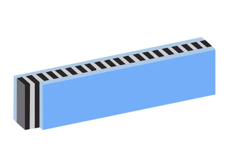
Dark gray or transparent insulating silicone on both sides helps improve side insulation and mechanical stability in thin designs.
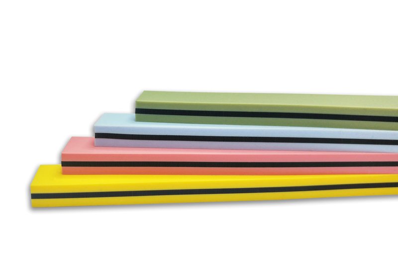
Non-standard strip designs can be made around special display layouts, contact positions, cushioning, and assembly spaces.
The connector works through pressure contact and controlled conductive silicone layers.
During assembly, the strip is compressed between the LCD and the PCB. This pressure lets the conductive layers touch the LCD ITO electrodes and PCB pads.
Current passes vertically through the conductive layers from the LCD electrode to the PCB pad, forming a stable low-current signal path.
The insulating layers separate adjacent conductive paths, so current cannot leak sideways into neighboring electrodes.
Silicone zebra connectors are produced by preparing insulating silicone and carbon-filled conductive silicone as separate sheet materials, then laminating them repeatedly to build the striped conductive structure. The combined thickness of one insulating layer and one conductive layer defines the connector pitch.
After lamination, the silicone block is vulcanized under controlled heat to bond the layers and stabilize elasticity. The cured block is then precision cut into strips according to the required length, width, height, and LCD-to-PCB contact layout.
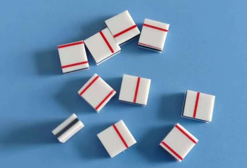
Electrical, physical, and environmental properties should be checked against the display module and assembly design.
| Property | Typical Guidance | Design Meaning |
|---|---|---|
| Conductive Layer Resistivity | About 3 to 15 ohm-cm | Lower resistivity means better conductivity for signal transmission. |
| Insulation Resistance | At least 10^12 ohms | High insulation resistance helps prevent leakage current and short circuits. |
| Maximum Current Density | About 2.5 mA/mm虏 | Suitable for low-current electronic signal circuits. |
| Hardness | Conductive layer about 65 Shore A | Hardness affects compression behavior and stable contact force. |
| Working Temperature | Typically -45°C to 150°C | Supports many display modules used in indoor, vehicle, and portable devices. |
| Compression Set | Often 30% or less under defined test conditions | Lower compression set helps the connector recover and maintain contact over time. |
Good zebra connector design starts with the LCD electrode, PCB pad layout, and target compression.
Common pitch options include 0.05 mm, 0.10 mm, and 0.18 mm. Each PCB pad should contact at least three conductive carbon layers.
Common conductive layer widths include 0.4 mm, 0.6 mm, 0.8 mm, and 1.0 mm. Wider layers usually increase hardness and reduce compression ratio.
Compression below 10% may make contact resistance unstable. Compression above 15% may deform the strip, LCD, or PCB.
Silicone zebra strips are widely used in compact products that need reliable LCD display connection without soldering.
Used in calculators, electronic watches, remote controls, game devices, and compact display products.
Used in multimeters, electronic scales, thermometers, hygrometers, and display-based measuring equipment.
Used for connections between vehicle display modules, instrument panels, and PCB assemblies.
Used in portable diagnostic devices, digital thermometers, and compact medical display modules.
A 2D drawing is the fastest way to confirm the silicone zebra connector structure. If a drawing is not available, send the specifications below and our team can review the conductive strip requirement.
These details help us confirm the construction and prepare an accurate quotation.
Send Zebra Connector RequirementsAttach the conductive zebra strip drawing or assembly cross-section if available.
State the required designation, such as GSS, GSG, GSI, or GSI2.
Provide the length, height, and width in millimeters.
Select 0.4, 0.5, 0.6, 0.7, 0.8, 0.9, or 1.0 mm, or specify another width.
Specify the combined pitch of one conductive and one insulating layer: 0.05, 0.10, 0.18, or 0.25 mm.
Share the expected quantity per order and estimated annual demand.
Let's talk about your project requirements. Fecision can review the design and recommend a practical zebra connector structure.