
FRP Core
E-glass or ECR glass fiber pultruded with epoxy resin. The core carries tensile and bending loads. ECR glass can be specified where electrical corrosion resistance is a priority.
Fecision manufactures composite insulators with an HTV silicone rubber housing, a load-bearing FRP core, and crimped galvanized steel end fittings for outdoor power systems.
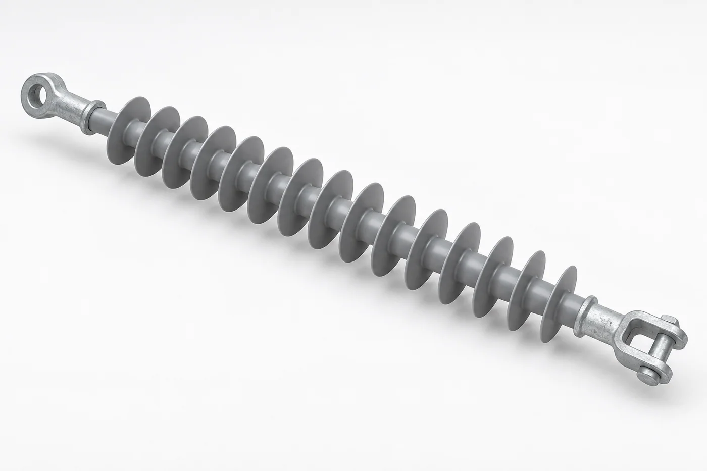
A silicone composite insulator is an electrical insulator built from three bonded parts: a fiberglass-reinforced plastic (FRP) core that carries the mechanical load, a silicone rubber housing with sheds that protects the core and provides creepage distance, and metal end fittings that connect the insulator to the line hardware.
Also called polymer insulators or composite line insulators, they support the conductor and keep current on the line like porcelain or glass insulators. Their non-brittle construction, hydrophobic surface, and low weight are especially useful where pollution, coastal exposure, difficult access, or installation handling affect the project.
Suspension, tension, line post, station post, and railway catenary formats can be reviewed against the specified voltage class, mechanical load, and installation geometry.
Interface quality is central to long-term reliability. Moisture entering between the silicone housing and FRP core can damage the interface and increase brittle-fracture risk, so bonding and sealing are treated as part of the primary design.
E-glass or ECR glass fiber pultruded with epoxy resin. The core carries tensile and bending loads. ECR glass can be specified where electrical corrosion resistance is a priority.
HTV silicone rubber injection molded directly onto the primed core. The housing protects against weather, UV, and pollution while establishing the required creepage path.
Ductile iron or forged steel with hot-dip galvanizing. Hydraulically crimped fittings connect to line hardware and transfer mechanical load into the FRP rod.
RTV silicone sealant with an elastomeric sealing element at the fitting mouth. This interface forms the moisture barrier at each end of the housing.
Material selection is tied to electrical, mechanical, environmental, and project-documentation requirements. Material certificates for the silicone compound, rod, and metal components can be included when specified in the order.
| Material | Typical Specification | Why It Is Selected |
|---|---|---|
| Silicone Rubber | HTV polydimethylsiloxane with ATH filler and fumed-silica reinforcement | Hydrophobic surface behavior; ATH supports tracking and erosion resistance. |
| FRP Rod | E-glass fiber and epoxy, with ECR glass available by project requirement | High tensile strength at low weight; ECR grades support applications with elevated brittle-fracture risk. |
| End Fittings | Ductile iron or forged steel, hot-dip galvanized to the specified coating standard | Transfers mechanical load and provides corrosion-resistant connection points. |
| Sealing System | RTV silicone sealant with a project-specified elastomeric sealing element | Maintains a flexible moisture barrier through outdoor exposure and thermal cycling. |
The process is simple to describe but sensitive to execution. Rod preparation, controlled priming, one-piece molding, crimping, and end sealing determine whether the interfaces remain stable in service.
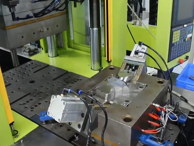
Composite construction separates the mechanical core from the external insulation surface, creating practical advantages for transport, installation, polluted environments, and custom line design.
A composite unit can weigh substantially less than an equivalent porcelain string, reducing tower load, transport effort, and handling requirements.
Silicone repels water and can transfer hydrophobic behavior to surface contamination, limiting formation of a continuous conductive water film.
The polymer housing does not shatter like porcelain or glass, reducing impact-related breakage during transport, installation, and service.
In suitable pollution classes, hydrophobic silicone can reduce reliance on routine washing. Maintenance planning still follows the utility's environment and inspection policy.
Shed diameter, spacing, profile, and overall length can be developed around creepage, voltage, pollution, and dimensional requirements without ceramic kiln constraints.
Configuration and material details are selected around the system voltage, installation load, pollution severity, altitude, corrosion exposure, and project standard.
Suspension and tension insulators for overhead line structures at the project's specified voltage and mechanical rating.
Dead-end, line post, and pin-type formats for urban and rural feeder systems.
Station post and application-specific composite insulation for switchgear, bus support, and transformer assemblies.
Composite insulators developed for overhead contact systems and railway electrification hardware.
Lightweight outdoor insulation for remote terrain and coastal renewable-energy installations.
Housing profiles for coastal salt fog, cement dust, petrochemical zones, and other high-contamination service conditions.
A complete quality plan distinguishes tests that qualify a design family from routine checks applied to production units. The exact plan is agreed against the insulator type, customer specification, and applicable standard.
Depending on the product type and market, the qualification plan may reference IEC 61109, IEC 60587, IEC 61952, or applicable ANSI C29 requirements.
Send the voltage class and project drawing for an engineering review.