
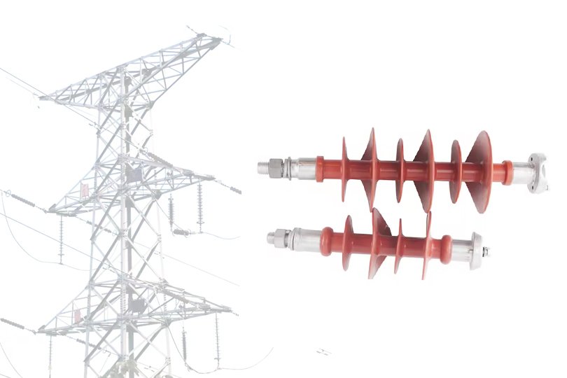
The reliable way to eliminate bubbles and black spots in silicone rubber composite insulators is an injection mold engineered around three features: a vacuum extraction unit that empties the cavity before liquid silicone rubber is injected, a split cavity built from individually machined blocks to handle complex shed profiles, and a controlled hot-fit assembly process with full mold sealing. This architecture directly addresses the two chronic defects of insulator production, internal voids that cause partial discharge and surface contamination that leads to corrosion discharge.
Why Silicone Composite Insulators Demand Defect-Free Molding
Rod-type suspension silicone rubber composite insulators are standard components on 10 to 1000 kV transmission and distribution lines, governed by standards such as IEC 61109. In high-voltage applications, insulation performance and surface finish are not cosmetic requirements. Any microscopic flaw, whether internal or on the surface, becomes a starting point for leakage current, creepage tracking, and partial discharge, which directly threatens the safety of line operators and equipment. This is why high-voltage apparatus must be manufactured without any microscopic internal or surface defects.
Yet the conventional integral injection molding process produces exactly these flaws. In a typical setup, liquid silicone rubber (LSR) is injected from the bottom of the mold and rises through the cavity. As it rises, the rubber converges from multiple directions toward the mold parting surfaces, and this converging flow inevitably generates a large number of bubbles. The bubbles travel upward with the viscous rubber, and during the curing process some of them fail to escape in time. They remain inside the product body or on the shed surfaces. Bubbles trapped inside the insulator cause internal discharge during service, while bubbles and pits on the surface trap contamination that later triggers corrosion discharge. Both defects substantially reduce the insulation performance and service life of the insulator and create serious safety hazards for transmission lines and equipment.
The structure of the product makes everything harder. To increase creepage distance, a composite insulator carries a large number of sheds, and this complex geometry is precisely what makes the mold difficult to design, difficult to machine, and expensive to modify. Poor mold quality then feeds back into poor product quality. Solving insulator quality problems therefore means solving mold engineering problems first.
2 Challenges in Composite Insulator Mold Design
Challenge 1: Machining Complex Insulator Shed Geometry
A composite insulator cavity contains numerous curved surfaces corresponding to the shed profile. Machining such a cavity as a single block exceeds the practical capability of conventional machine tools, and every design change becomes a costly rework of the entire cavity.
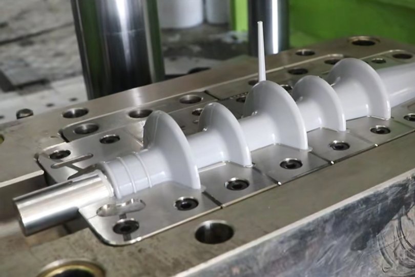
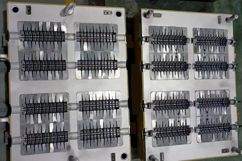
The engineering answer is to break the complex cavity down into simple, machinable feature units. Each shed feature is designed as an individual insert block, machined separately on standard equipment, and the finished blocks are then assembled into the mold body to form a complete half mold. A production mold of this type typically contains around 20 such blocks. This approach converts an unmachinable cavity into a set of routine machining operations and makes future modifications a matter of replacing one block rather than reworking the whole mold.
Challenge 2: Trapped Air and Bubbles in LSR Injection Molding
The bubble problem originates in the injection step itself. Air sits inside the closed cavity before injection; when LSR enters, it mixes with that trapped air, and the mixture cures with bubbles locked inside the silicone.
The key to solving this is to empty the cavity of air before the material arrives, and to make sure no outside air can re-enter during injection. This imposes two requirements on the mold design. First, the mold must seal completely when the two halves close. Second, a vacuum extraction unit must be fitted at the top of the mold: after the mold closes, the air inside is fully extracted until the cavity reaches a vacuum state, and only then does injection begin. With no air in the cavity, the rising silicone generates no new bubbles. Moreover, vortex air pockets hidden inside the injected material expand in volume under vacuum, which causes them to be preferentially squeezed out at the top of the mold as the material converges and tumbles through each cavity section. After curing, neither the interior nor the surface of the insulator contains microscopic bubbles.
Mold Structure for Composite Insulators
A production-grade injection mold for rod-type suspension composite insulators is configured for both output and quality. The mold is built with two cavities, so one injection cycle produces two insulators. Structurally it is a left-right split mold: the silicone injection port sits at the bottom, and the vacuum extraction unit sits at the top. To keep the cavity manufacturable, every shed feature in the mold is designed as a separate block; each block is machined individually, and the blocks are finally fixed into the cavity with fastening screws to complete the mold assembly.
This layout solves three problems at once: the two-cavity design lifts productivity, the top-mounted vacuum unit guarantees a bubble-free cavity environment, and the modular shed blocks keep a highly complex cavity within the reach of ordinary machining equipment.
5 Composite Insulator Manufacturing Challenges and Solutions
Building and assembling this mold presents five specific technical difficulties, and each one has a corresponding engineered solution.
Step 1: Split Cavity Block Design for Insulator Shed Profiles
Because the shed structure is complex, the shed portion of the cavity cannot be finish-machined on a machine tool in one setup. Where the blocks are split determines whether they can be machined at all. The proven splitting method places the boundary at the 180-degree quadrant point of the arc at the end of the shed profile feature. This divides the shed cavity into two conical surfaces joined by a semicircular transition. Once split this way, the resulting geometry can be turned on an ordinary CNC lathe, and the dimensional and geometric tolerances of the shed can be held with ease.
Step 2: Deep Cavity Milling
The insulator mold cavity is deep, and during milling the cutter shank must extend a long way into the workpiece. A long, slender shank deflects under cutting load, which produces the classic defect of cavity walls that are not perpendicular to the cavity base. Two measures in combination solve this problem. First, increase the rigidity of the milling cutter by using a specially made, strengthened shank. Second, abandon aggressive cutting in favor of multiple passes at small feed rates. With a rigid cutter and a light, stepped milling strategy, the perpendicularity of deep cavity surfaces can be fully guaranteed.
Step 3: Preventing Shed Misalignment in Split Block Mold Assembly
When pre-machined blocks are placed into the cavity, the fit between each block and the cavity must be dimensioned correctly, and the dimensional and geometric tolerances of every block must be carefully calculated or verified by simulation at the design stage. Otherwise, once the blocks are installed, the sheds on the left and right mold halves will be misaligned, and every boundary where the flow fronts meet on the product will come out rough.
The solution is a strictly controlled machining and assembly sequence. First, finish-machine the shed profile features inside each block so that the internal shape of every shed cavity fully meets its dimensional and geometric tolerances. Then assemble the blocks together and verify that the shed cavities show no misalignment against each other. Only after this verification are the outer surfaces of the assembled blocks milled to size. During this final milling, the outer dimensions of the blocks are deliberately left with a positive allowance, so that when the blocks are later fitted into the mold body they form an interference fit, which is what locks the whole assembly against movement during injection.
Step 4: Hot-Fit Assembly Temperature Control
The blocks and the mold body must assemble with tight, leak-proof joints, and this is achieved by hot-fit (shrink) assembly, which requires heating the mold body so it expands enough to receive the blocks. The heating temperature is not chosen by experience alone; it is calculated from the thermal expansion coefficient of the P20 mold steel together with the designed interference of each block. In practice, the cavity heating temperature is controlled at 220 to 260 degrees Celsius.
Temperature discipline here directly determines product appearance. The heating temperature must never be set too high, because an overheated cavity oxidizes easily, and oxide scale formed on the cavity surface will solidify onto the product during injection as black spots, a defect that seriously damages both appearance and quality. At the same time, the mold must be protected against rapid cooling during the hot-fit process, so thermal insulation measures must be planned into the assembly operation to keep the body at temperature until every block is seated. If a block with a large interference proves difficult to assemble, the correct response is to reduce the interference allowance of that block appropriately rather than to push the heating temperature higher.
Step 5: Injection Mold Sealing Design
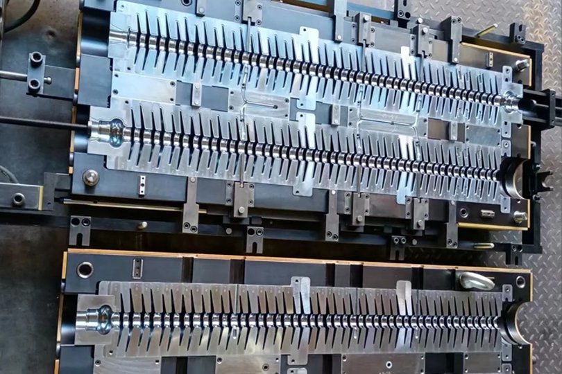
A vacuum extraction unit only works if no outside air can enter the cavity during injection, and this mold is an unusually demanding sealing case. The parting line of the closed mold is long, roughly 20 internal blocks must be fixed inside the cavity with screws, and the core shaft has to extend out of the mold body, creating complex joint surfaces at multiple locations. Three sealing points must therefore be engineered.
The first is the seal between the two mold halves along the closing line, which is handled by installing a custom silicone rubber sealing ring along the parting surface. The second is the sealing of the screws that fix the blocks inside the cavity; each screw is fitted with a silicone rubber sealing ring so that the threaded penetrations cannot admit air. The third is the seal where the core shaft exits the mold. Rather than sealing the shaft penetration in isolation, the shaft is fixed inside the vacuum extraction unit itself, so the exit point sits within the evacuated zone and no separate sealing element is required there. With all three locations sealed, the cavity holds its vacuum from the moment the mold closes until injection is complete.
Solving the air problem at the mold level changes the quality profile of the product. Because the cavity is evacuated before injection and sealed throughout, the cured insulator contains no microscopic bubbles internally and none on its shed surfaces, which removes the initiation points for internal discharge and contamination-driven corrosion discharge. Because hot-fit temperatures are calculated and controlled, the cavity steel never oxidizes, so black spots disappear from the product surface. Because the shed blocks are machined individually at the 180-degree quadrant split and assembled under a verified sequence, the shed boundaries on the product come out smooth, the effective creepage distance increases, and both insulation performance and appearance improve markedly.
The mold itself becomes cheaper to build and far easier to maintain. A split-block cavity avoids the extreme machining difficulty of an integral cavity, and when a shed profile needs revision, only the affected block is reworked or replaced. For insulator manufacturers, this combination of quality and tooling economics is what turns a chronic production bottleneck into a repeatable, controllable process.
Conclusion
Design the vacuum extraction and the sealing system as one package, because vacuum without sealing is an invisible leak and sealing without vacuum leaves the bubbles in place. Split complex cavities into simple feature blocks, and place the split at the 180-degree quadrant point so ordinary CNC lathes can hold the shed tolerances. Treat hot-fit heating temperature as a product quality parameter rather than a shop-floor convenience, since it is the dividing line between a clean surface and black-spot scrap. And control the assembly sequence strictly: finish the internal shed profiles first, verify alignment across the assembled blocks, then machine the outer fit surfaces with a positive allowance for interference fit.
Producing void-free composite insulators requires a mold partner with split-block cavity engineering, vacuum system integration, and disciplined hot-fit process control under one roof. Fecision silicone can design and build injection molds for silicone rubber composite insulators across the 10 to 1000 kV range, from DFM review through tooling and trial production.
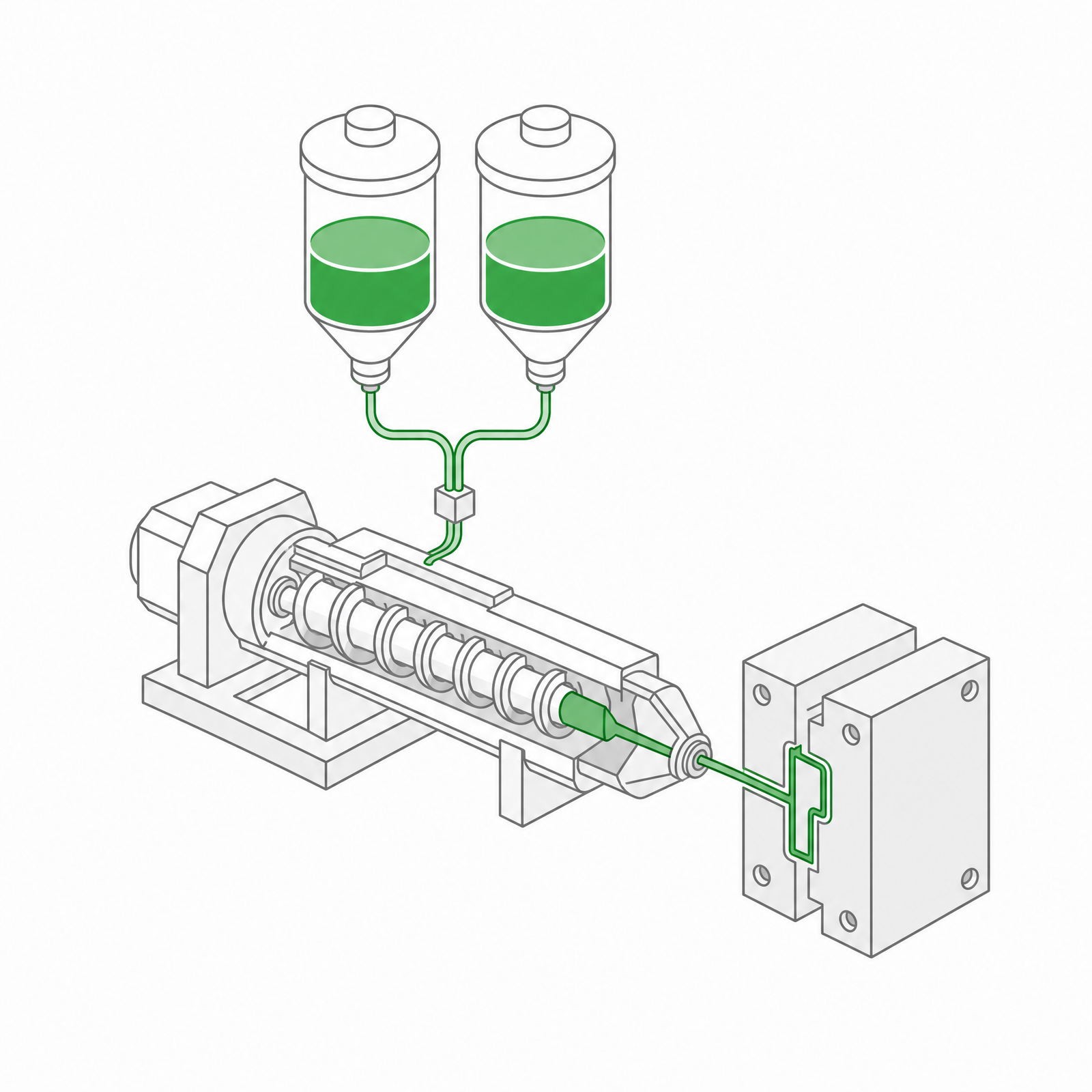 LSR Injection Molding
 Silicone Rubber Overmolding
 Compression Molding
 Silicone Rubber Extrusion
 In-house Tooling