

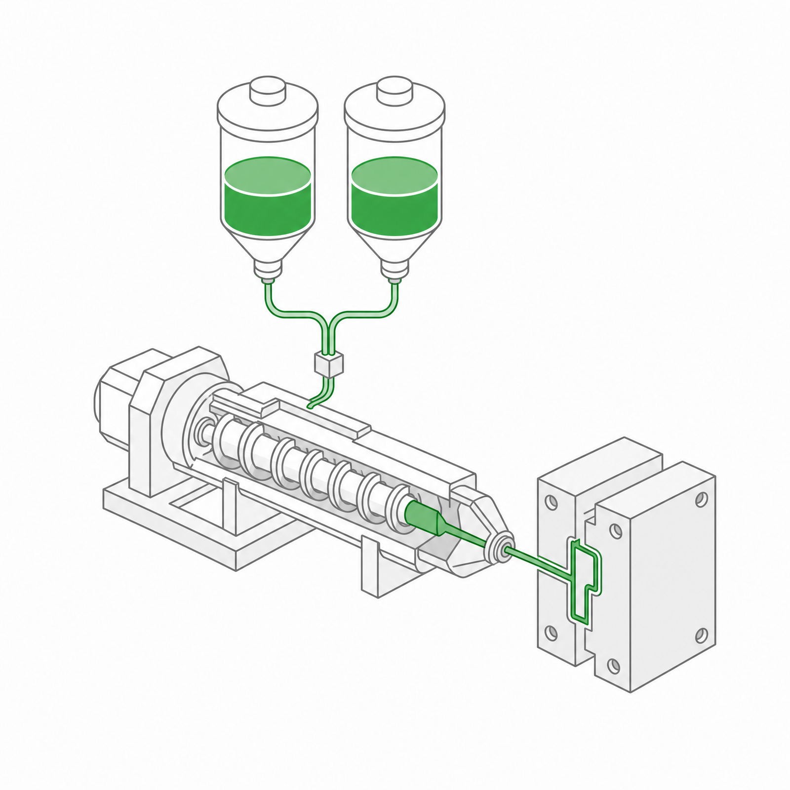
Liquid silicone rubber (LSR) flows into the cavity at low viscosity and cures in a heated mold. It fills fine features but also enters small gaps at shutoffs. Thick sections take longer to cure. During demolding, thin edges and undercuts stretch as the part separates from the steel.
For LSR injection molding, the DFM report defines the material grade, wall sections, parting line, gate and vent positions, release method, and inspection requirements before tooling. Open issues are resolved through a drawing change, a tooling decision, or a documented trial requirement.
1. Material Selection
Material Grade and Hardness
A hardness callout such as 50 ±5 Shore A leaves several material properties unspecified. Grades with the same hardness can differ in viscosity, tear strength, elongation, shrinkage, adhesion, and release behavior. The tooling review requires a selected grade and a defined pigment or additive package.
Grades around 30–70 Shore A cover many general-purpose parts. At thin walls and sharp corners, low tear strength leads to tearing during release. A grade with limited elongation can split when stretched over an undercut. The DFM report pairs the selected grade’s tear strength and elongation with the release geometry. Cured hardness alone does not establish filling pressure; the pressure calculation uses uncured viscosity, flow length, and wall thickness.
Shrinkage Allowance
LSR shrinkage is commonly estimated at 2–3% for early design calculations, with some grade and process combinations reaching about 3.5%. The selected grade’s data sheet supplies the initial tooling value. Mold temperature, cavity pressure, demolding temperature, flow direction, and post-curing all change the measured result. Flow-direction and transverse dimensions are recorded separately during trials because shrinkage is not always uniform in both directions.
For a 20 mm reference dimension, a first-order calculation gives approximately 0.20 mm of dimensional error for a one-percentage-point error in the assumed linear shrinkage. With a specified tolerance of ±0.05 mm, this error is four times the allowance in one direction.
Trial parts use the production pigment, molding conditions, and post-cure. Data from an existing tool is useful when the grade, section thickness, and flow arrangement match the new part. The measured allowance is then corrected during sampling before final dimensional approval.
Post-Curing and Appearance
The material documentation and product specification establish whether post-curing is required, its temperature, and its duration. Medical, food-contact, and low-volatile applications require this decision before quotation. Omitting a required post-cure understates processing cost and leaves its additional shrinkage out of the tolerance calculation.
Thicker sections take longer to heat and release volatiles during post-curing. Final dimensional approval uses parts after the specified treatment, not dimensions measured directly after molding.
Color distinguishes similar parts and can improve contrast during handling and optical measurement. Transparent parts require defined surface finish, bubble acceptance criteria, lighting, and edge detection. The DFM record includes the appearance criteria and measurement method. Voids that affect strength or sealing remain defects regardless of part color.
2. Wall Thickness
Wall Range and Thin Sections
A CAD thickness map identifies thin flow restrictions and local thick sections. The recommended wall thickness for conventional LSR parts is 0.5–6 mm. Sections above 6 mm take significantly longer to cure and extend the molding cycle.
Localized walls down to approximately 0.2 mm are achievable. The thin area, flow distance, and position of adjacent thicker sections determine whether material reaches the feature before curing blocks the feed path. A short thin section fed by an adjacent thicker wall is easier to fill than a broad panel of the same thickness. Below 0.3 mm, flow resistance and filling-pressure demand rise sharply; 0.3 mm is not an absolute minimum wall thickness.
Uncured LSR is shear-thinning: its apparent viscosity decreases as shear rate increases during injection. This helps material pass through thin sections and allows more variation in wall thickness than is usual in thermoplastic part design. Thick regions still add curing time, and sudden section changes can trap air.
Ribs and Internal Radii
Rib thickness is normally 0.5–1.0 times the adjacent wall thickness. For a 1.0 mm wall, the corresponding rib is 0.5–1.0 mm thick. This ratio limits excess material at the rib root while providing support. A heavier rib root forms a local thick section and lengthens curing time.
The internal fillet radius is normally close to the adjacent wall thickness. For a 1.0 mm wall, an internal radius near 1.0 mm provides a gradual transition. An oversized fillet adds a local mass; an undersized fillet leaves an abrupt flow change and a tear-sensitive corner. Corner porosity is investigated together with air entrapment, venting, and filling conditions rather than attributed to radius alone.
Milled cavity corners retain a radius set by the cutter geometry. The toolmaker identifies these radii before machining and records any change to the molded contour in the approved model or drawing. A functional sharp feature requires a defined tooling method, such as an EDM-machined detail or a separate insert. The CNC program does not authorize an unrecorded change to the part geometry.
Thickness Transitions and Cure Time
The mold cannot open until the thickest section has cured enough for removal. A local mass therefore delays the entire part, even when the remaining walls are already cured. Hollow bosses, cored mounting features, and reduced transition sections remove this excess material. The main penalty for unnecessary thickness is longer curing time, rather than the sink marks associated with thermoplastic parts.
Wall transitions use radii or gradual changes in section. The DFM report marks local sections exceeding 1.5 times the main wall thickness for a cure-time calculation or simulation. Thick areas that exceed the cycle-time target are cored or reduced; any retained thickness is included in the production cycle and quotation.
Lower-viscosity grades reduce resistance through fine features but also flow more readily through shutoff gaps. Changing to a lower-viscosity grade therefore requires a corresponding check of the shutoff fit and flash limits.
3. Parting Lines and Shutoffs
The parting line is the trace left where mold sections meet at the part surface. Accurate fitting limits flash, but a fitted interface can still leave a visible witness line. Its position is chosen around sealing contact, cosmetic faces, and the release direction. A flat, accessible split is generally easier to machine, fit, and maintain than a complex three-dimensional interface.
Gaps as small as 0.005 mm can produce LSR flash. Shutoffs must remain closed at molding temperature and under cavity pressure. A fit that closes during cold assembly but opens after heating or injection will leak. Tool alignment, thermal expansion, and wear are included in the fit calculation.
Parting lines are placed outside the sealing contact band. Flash across that band interrupts contact and creates a leakage path. Where the structure prevents relocation, the drawing defines the permitted flash thickness, extension, direction, and trimming method. The resulting surface must pass the specified assembly or leakage test.
Shutoffs around inserts and cores require a tolerance stack that includes insert size and position, mold alignment, and thermal expansion. Excess clearance produces flash. Excess interference can damage the insert or tool. Incoming insert variation forms part of this assessment.
Multi-part tooling can add secondary parting lines to release features that a two-piece mold would lock or drag across an edge. Each added split creates another shutoff and witness line. The tooling decision identifies the feature it releases and keeps the added line outside the sealing contact band.
4. Demolding
Draft and Elastic Release
Simple, rounded LSR undercuts can be stripped manually without a sliding core. Production tooling uses elastic stripping or moving tooling according to the required release motion. Air assistance, stripper plates, and robotic pickup form part of that design, with positions and operating sequence established before the tool is built.
A 0.5–1° draft reduces drag on smooth vertical faces. Deep cavities and textured surfaces need additional release clearance because they retain more contact during removal. Zero-draft features require a defined stripping path and a release method that separates the part without tearing the wall.
The DFM drawing marks each undercut and its stripping direction. The release calculation uses the opening size, undercut depth, wall thickness, and available stretch length. Sharp edges along this path cut or tear the silicone. The toolmaker confirms that the selected grade can pass over the core at demolding temperature. Where the required strain exceeds the material’s release capability, the design uses a moving core or a shallower undercut.
For a circular opening, passing a 10 mm opening over a 12 mm core requires a 20% increase in circumference: (12 ÷ 10 − 1) × 100%. Local strain at corners and thin edges can be higher. The calculation gives the stretch required by the core geometry. Release trials establish whether the selected grade withstands that stretch at demolding temperature without tearing or permanent deformation.
Sticking and Part Handling
Deep ribs, narrow columns, and large contact areas increase sticking and release force. The mold retains the part on the side intended for removal. Deep steel surfaces are polished along the release direction to reduce drag; polishing across the release path leaves tool marks that resist stripping.
Restrictions on external release agents are recorded before tooling. Where cleanliness or bonding requirements prohibit them, mold finish and release geometry must provide demolding without the agent. Grippers that squeeze a soft wall deform the part during pickup. A dedicated gripper or support fixture distributes the load and is included in the automation cost.
5. Gates and Venting
The drawing identifies each gate location and the maximum permitted vestige. Gate marks are kept away from sealing contact and assembly clearances. Cold-runner systems with valve gates feed the heated cavity while keeping material in the runner uncured between shots.
Material starts curing as it enters the heated cavity. Remote features must fill before the flow path cures shut. Multiple gates create meeting points between flow fronts. Those points need an air escape path; otherwise, trapped air produces voids or incomplete filling.
LSR vent depths are controlled at the micrometer scale. A vent that is too deep produces flash; a vent that is too shallow or blocked traps air. The toolmaker sets the vent depth and land length, then checks air removal and flash during trials. Parting-line vents serve accessible flow ends. Vented inserts, cores, or vacuum channels serve regions outside that path.
Flow ends, rib junctions, and deep pockets are checked for air traps. Vacuum evacuation requires a connected path from these regions to the vacuum system. Overflow-well connections are placed in approved nonfunctional areas, with a defined method for removing the resulting tabs.
LSR filling and curing simulation checks two results: whether the final flow ends coincide with vent locations, and how long the slowest section takes to cure. A flow end away from a vent requires a gate or vent change. A thick section that extends the cycle requires a geometry change or an accepted increase in production time. Mold trials verify these results.
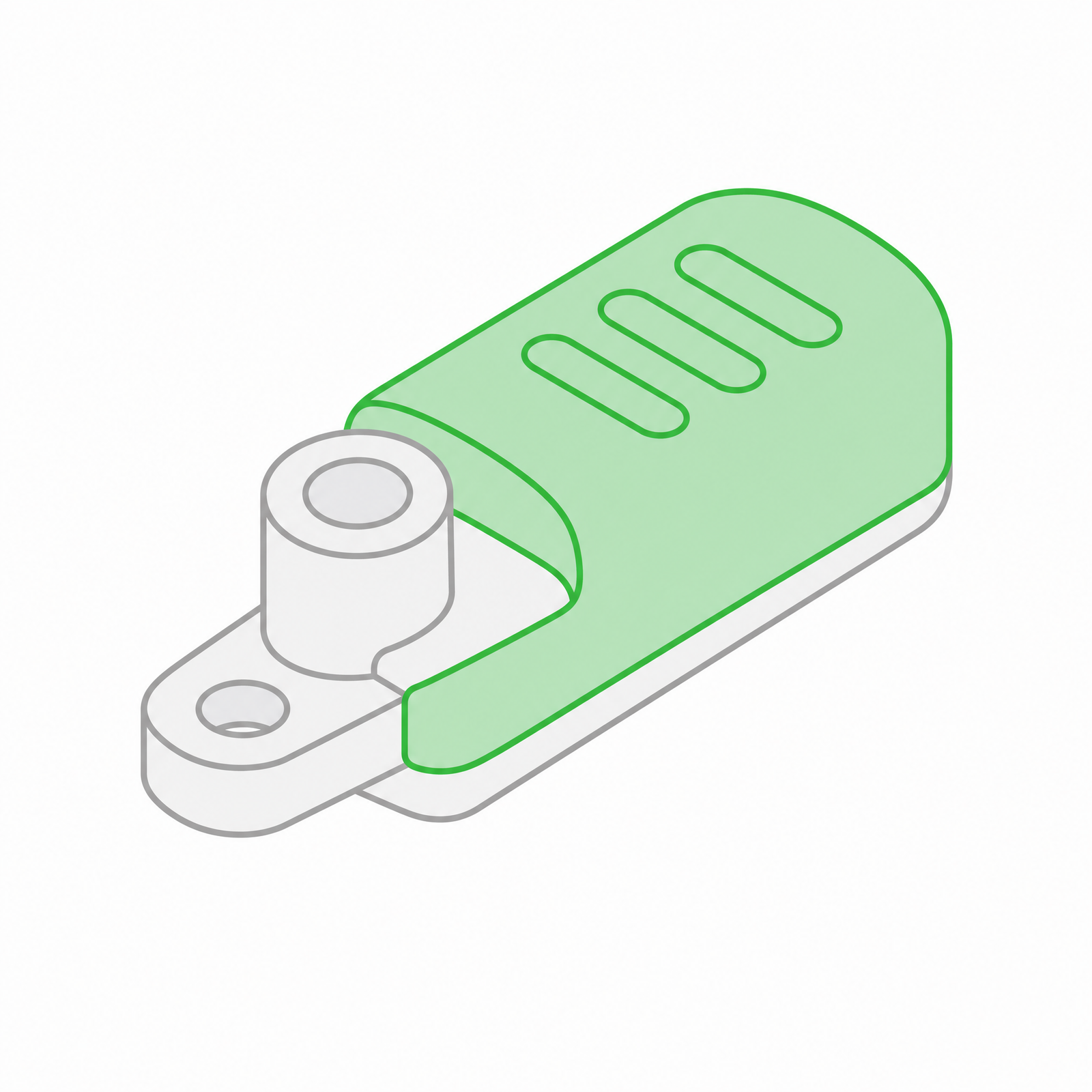
6. Insert Overmolding
Insert overmolding adds bonding, heat transfer, and insert location requirements to the shutoff design.
- Bonding: Standard LSR does not form a reliable bond to most substrates without a bonding system. The design specifies a compatible self-bonding grade, a surface-treatment and primer process, or mechanical retention. Adhesion is tested on the production substrate and finish.
- Temperature: The insert must withstand the molding cycle and any post-cure. Conventional LSR molds commonly run at 160–200°C. A cold insert removes heat from the adjacent silicone and delays local curing. The process sheet specifies any preheating temperature and loading time needed to control this heat loss.
- Location: The mold supports the insert against injection forces. Insert size, position, and thermal expansion form one tolerance stack at the shutoff. Excess clearance causes flash; excess interference crushes the insert or damages the tool.
- Process compatibility: Cleaning, primer application, drying, and loading are defined operations with specified times. Insufficient drying or contamination causes bonding or cure defects. Their cycle times are included in the production-rate calculation.
Sampling uses the specified insert material and surface condition. Changes to the plastic grade, coating, or metal finish require review of their effect on adhesion.
7. Dimensions and Inspection
Dimensional Tolerances
The drawing identifies dimensions that control assembly and performance. These may include openings and cavities as well as solid sections. Flexible internal features require defined measurement conditions and support.
ISO 3302-1 tolerance classes apply where the product falls within the standard’s scope. The drawing or agreed tolerance table defines the acceptance limits by nominal size and dimension classification. A general ±0.1–0.2 mm allowance or percentage rule does not replace this specification. Precision O-rings require their applicable dimensional specification.
A ±0.05 mm requirement is not accepted on tooling accuracy alone. Trial measurements must show both process repeatability and a measurement error small enough to resolve the tolerance. If either condition fails, the drawing needs a wider tolerance, a different inspection method, or a functional assembly criterion before production approval.
A shallow arc provides too little geometry to locate its center repeatably. A short reference edge gives an unstable angle measurement. A theoretical tangent point has no physical edge for a probe to locate. These dimensions are replaced with accessible datums or designated as reference dimensions when they do not control function. Functional features retain acceptance limits and use a defined gauge or test.
Measurement Conditions
Dimensional approval uses the finished part after any specified post-cure. A practical room-temperature inspection condition is at least 24 hours at 23 ±2°C and 50 ±5% RH before measurement. The drawing or inspection specification records the agreed condition so all samples are measured after the same treatment and conditioning period.
The specification distinguishes free-state measurement from measurement in an assembly fixture. Contact probes can deform soft silicone. Optical measurement is affected by transparency and edge contrast. Support, clamping force where relevant, lighting, and orientation are defined to control measurement variation.
Critical dimensions control assembly or part performance and are measured during production. Cpk calculations require a verified measurement system; inconsistent fixturing produces measurement scatter that cannot be separated from process variation. Where either location meets the functional requirement, a dimension on an insert-supported or thicker section is easier to control than one on an unsupported flexible edge.
The completed DFM record contains the agreed material, geometry, gate locations, flash limits, demolding method, and inspection requirements. Changes confirmed during sampling are incorporated into the production drawing and acceptance criteria.
 LSR Injection Molding
 Silicone Rubber Overmolding
 Compression Molding
 Silicone Rubber Extrusion
 In-house Tooling