
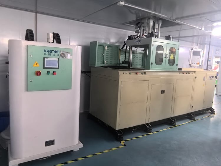
Liquid silicone rubber injection molding can produce highly consistent parts with thin walls, complex sealing features, fine surface details, and tight dimensional requirements. However, the process is sensitive to the interaction between material metering, A/B mixing, injection conditions, mold temperature, cold-runner control, venting, vacuum, curing, and demolding.
A visible defect does not always point directly to its root cause. A short shot may result from insufficient material, but it can also be caused by trapped air or premature curing. A bubble may originate in the material supply system or form because cavity air cannot escape. Flash may be caused by excessive injection pressure, but it may also indicate a damaged parting line or an incorrectly designed vent.
For this reason, LSR troubleshooting should focus on the physical mechanism behind the defect rather than changing individual machine settings at random.
The following 17 defects cover many of the problems encountered in production LSR molding.
1. Short Shot or Incomplete Filling
A short shot occurs when the injected LSR does not completely fill the cavity. The missing area is often found at the end of the flow path, around thin sealing lips, narrow ribs, small holes, or other features with high flow resistance.
The first parameter to verify is actual shot volume. In an LSR system, unstable material feeding, low pump pressure, incorrect metering, valve malfunction, or restrictions in the mixer, nozzle, cold runner, or gate can reduce the amount of material reaching the cavity. Injection speed and pressure also affect filling, particularly in thin-wall or long-flow applications.
Mold temperature can contribute as well. LSR requires heat for rapid crosslinking, but an excessively hot cavity may cause the material near the gate or cavity wall to begin curing before filling is complete. Once viscosity rises, the remaining flow distance decreases.
Poor venting produces a similar appearance. If cavity air cannot escape, it creates back pressure against the advancing silicone. In this case, simply increasing injection pressure may fill the part but create flash somewhere else.
A more reliable troubleshooting sequence is to verify shot volume and A/B feeding first, then inspect the material path and gate, confirm venting and vacuum performance, check actual cavity temperature, and only then optimize the injection profile.
2. Air Traps
Air traps occur when air inside the cavity becomes enclosed by the advancing LSR and cannot reach a vent or vacuum path before the flow fronts meet.
Typical locations include the last-fill area, deep ribs, blind features, sections surrounding inserts, thin membranes, and regions where two or more flow fronts converge.
The main causes are poor vent location, blocked vents, insufficient mold vacuum, unbalanced flow, and unsuitable injection speed. Filling too quickly can compress air before it escapes, while filling too slowly can allow the silicone in contact with the hot mold to begin curing before the remaining cavity volume is filled.
Gate location is particularly important. If the gate creates several competing flow fronts, the mold may repeatedly trap air in the same area even when injection pressure and vacuum appear normal.
For complex diaphragms, valve structures, connector seals, and other thin LSR parts, gate and vent positions should ideally be evaluated during DFM. Correcting an air trap through tool design is usually more robust than compensating for it with machine settings.
3. Bubbles and Blisters
Bubbles and blisters may look similar to air traps, but the gas can originate before the material reaches the cavity.
Air may enter the LSR through drum changes, follower plates, pump seals, feed hoses, color-dosing equipment, loose connections, or unstable metering. If the bubble location varies randomly from part to part, the material supply system should receive particular attention.
If bubbles repeatedly appear in the same location, the mold itself becomes a stronger suspect. Poor venting, insufficient vacuum, or a flow pattern that closes off an air pocket can produce consistent bubble defects.
Cure conditions should also be checked. A locally under-cured section may deform after demolding and develop a blister-like appearance even when no obvious air bubble was visible when the mold opened.
Corrective action should therefore begin with the material delivery system, followed by mold vacuum, venting, injection speed, and actual cure conditions. Introducing liquids or release sprays into the cavity is not a suitable general solution for LSR injection molding and may create additional contamination or cure-inhibition problems.
4. Excessive Flash and Difficult Deflashing
LSR has very low viscosity before curing and can penetrate extremely small gaps. This makes flash control highly dependent on mold precision and process stability.
Excessive flash can result from too much shot volume, excessive cavity pressure, inappropriate pressure switching, insufficient clamping force, oversized vents, damaged parting surfaces, mold deflection, insert misalignment, or wear in shut-off areas.
The location of the flash helps identify its cause. Flash appearing around most of the cavity usually suggests a process-related issue such as shot volume, pressure, or clamping. Flash that repeatedly develops in one local area is more likely to indicate parting-line damage, an oversized vent, misalignment, or a local tooling defect.
Difficult deflashing is particularly problematic around sealing lips, thin membranes, cosmetic surfaces, and small functional edges. If the flash becomes too thick, removing it can tear or deform the part itself.
For precision LSR components, flash should therefore be controlled primarily through LSR mold design, shut-off accuracy, vent dimensions, cavity pressure, and shot consistency rather than relying on secondary trimming.
5. Pre-Cured Material or Cured Particles
Pre-cured material appears as hard silicone fragments, gel particles, transparent inclusions, or partially crosslinked material embedded in the molded product.
The underlying mechanism is premature crosslinking before the LSR reaches the intended cavity location.
Typical sources include the static mixer, injection unit, nozzle, valve gate, cold-runner manifold, and especially the thermal transition between the cooled runner and the heated mold.
Temperature and residence time are the key variables. If mixed LSR remains too long in a warm section of the system, it can begin curing. Excessive shear can also contribute by increasing local material temperature.
The cooling circuit, nozzle temperature, runner temperature, mixer condition, residence time, and stagnant areas should all be checked. Production interruptions deserve special attention. When cured particles appear mainly in the first few shots after a stoppage, material that remained close to the hot mold interface is a likely source.
Regular preventive cleaning is preferable to waiting until accumulated cured material begins entering production parts.
6. Foreign Particles and Contamination
Foreign contamination can appear as black specks, fibers, dust, cured silicone fragments, metal particles, or particles of another color.
The source may be the raw material, but contamination frequently enters later in the process. Possible sources include dirty feeding equipment, old material in the mixer or nozzle, worn machine components, contaminated molds, gloves, wiping materials, compressed air, maintenance operations, or poor handling practices.
A repeated particle appearing in approximately the same position should lead to inspection of the mold, runner, or injection system. Random contamination across different cavities is more likely to come from the environment or material-handling process.
For medical and cleanroom LSR components, contamination control should cover the entire manufacturing chain from material storage and feeding through molding, demolding, inspection, and packaging.
In these applications, equipment-cleaning procedures, controlled compressed air, operator discipline, cleanroom practices, and traceable material handling become part of process capability rather than simple housekeeping.
7. Tearing and Cracking
LSR parts may tear during demolding even when they appear normal inside the cavity.
The first question is whether the silicone itself has insufficient mechanical strength or whether the mold is mechanically overstressing the part during removal.
Under-cured LSR can have reduced tear resistance. Actual cavity temperature, cure time, A/B ratio, and possible cure inhibition should therefore be verified first.
If curing is normal, the mold geometry becomes more important. Deep undercuts, sharp corners, small holes, rough surfaces, insufficient draft, poorly positioned grippers, or an aggressive stripping direction can concentrate strain in a small area.
Very soft LSR can tolerate substantial deformation, but that does not mean every geometry is easy to demold. Good tooling allows the part to deform gradually instead of forcing a thin feature to carry most of the extraction load.
Changing to a harder material may hide the problem but can negatively affect sealing, tactile response, or other functional requirements.
8. Color Variation and Color Spots
Color variation usually originates from pigment dosing, dispersion, batch control, contamination, or thermal variation.
A colored LSR process depends on a stable relationship between the base silicone flow and the pigment or color masterbatch. An unstable dosing pump, partially blocked feed point, inconsistent pigment concentration, or incorrect dosing ratio can create part-to-part color variation.
Poor mixing may produce streaks or localized spots even when the total pigment amount is correct. The color-dosing unit, injection location, static mixer, and material flow path should therefore be evaluated as one system.
Cross-contamination between colors or material batches is another common source of variation.
Mold temperature and cure history can also influence the appearance of some pigment systems. For products with strict cosmetic requirements, surface finish and visual inspection alone are usually insufficient. Instrumental color measurement using an agreed Delta E tolerance provides a more repeatable method for controlling production.
9. Surface Blooming or Whitening
Surface blooming appears as a white, hazy, powder-like, or cloudy condition on the silicone surface.
It should be distinguished from white marks created by trapped air or abnormal flow. The appearance may be similar, but the root cause is different.
True blooming is usually associated with components migrating toward the surface. Possible causes include formulation imbalance, excessive concentration of certain additives, incompatible pigments or processing chemicals, contamination, poor dispersion, or incomplete curing.
If the defect appears after a change in material, pigment, additive, cleaning agent, or release agent, compatibility should be investigated first. If additional curing reduces the problem, the original cure state should also be checked.
Timing is useful during diagnosis. A defect that gradually develops during storage is more consistent with migration or blooming, while a white mark that appears immediately at the same location in every cavity may be related to filling or trapped air instead.
10. Warpage and Deformation
LSR is flexible, but the molded geometry can still become permanently or temporarily distorted.
Long parts may twist, membranes may curl, thin walls may collapse, and sealing lips may deform after demolding.
Insufficient cure is one possible cause because the part may be stretched during removal before the silicone has developed enough mechanical strength. Uneven mold temperature, unbalanced filling, local residual stress, and premature demolding can also contribute.
Handling after molding is equally important. Very soft parts are often still hot when they leave the mold. If they are stacked, compressed, or stored in an unsupported position before cooling, the final geometry can shift even though the molding cycle itself was stable.
For delicate parts, the solution may involve better part handling or cooling fixtures rather than additional changes to injection pressure or mold temperature.
11. Weld-Line Separation
When two LSR flow fronts meet, they must still have enough mobility and curing compatibility to form a strong, continuous section.
If one or both flow fronts begin crosslinking before they meet, or if contamination exists at the interface, the resulting weld line may become mechanically weak. The part may later split or separate along this line during stretching, assembly, or functional testing.
Poor gate location, unbalanced runners, excessive mold temperature during filling, low filling speed, trapped air, contamination, or unstable injection conditions can all contribute.
The corrective strategy should focus on improving the filling pattern. Gate location, runner balance, injection speed, venting, vacuum, and thermal conditions should be evaluated together.
This defect should be distinguished from true delamination in LSR overmolding. When silicone separates from a metal, plastic, FPC, or other substrate, substrate compatibility, surface preparation, primer, insert temperature, and bonding chemistry also need to be investigated.
12. Flow Marks and Surface Lines
Flow marks may appear as visible lines, streaks, gloss changes, or texture differences on the molded surface.
They usually indicate that the material did not flow through the cavity under uniform conditions.
Too low a mold temperature may reduce surface replication or delay proper cure. Too high a temperature may cause early skin formation before filling is complete. Poor gate location, runner imbalance, injection-speed changes, air evacuation problems, and sharp thickness transitions can also create visible flow patterns.
Colorant dispersion may make the defect more obvious in pigmented silicone even when the flow behavior itself has not changed substantially.
The location of the mark relative to the gate and the end of fill provides useful diagnostic information. Adjustments should therefore be based on the actual filling pattern rather than applying the same temperature or pressure change to every flow-mark problem.
13. Pinholes
Pinholes are small defects, but they can create serious failures in membranes, valves, diaphragms, medical components, waterproof seals, and pressure-containing silicone parts.
Possible causes include microbubbles, foreign particles, pre-cured silicone, mold contamination, or incomplete filling in very thin sections.
One especially important mechanism is a small cured particle entering a thin membrane. The finished part may initially look acceptable, but stretching or pressure loading can expose a pinhole around the inclusion.
Mold cleanliness, material cleanliness, feed-system condition, and cold-runner control are therefore particularly important for very thin LSR parts.
For sealing applications, visual inspection alone may not provide sufficient assurance. Depending on the product, verification may require pressure-decay, vacuum-decay, air-leak, water-ingress, burst, or other functional testing and validation.
14. Abnormal Hardness
Unexpected Shore hardness should first lead to inspection of material identity, A/B metering, additive dosing, and cure completion.
Most LSR materials are supplied as controlled two-component systems. Their nominal hardness is primarily determined by formulation rather than by machine settings.
If a molded part is softer than expected, check whether the correct material grade was used, whether the A/B ratio is correct, and whether the part has fully cured. Pump imbalance, feed restriction, air in the material system, or metering problems can disturb the intended ratio.
If the measured hardness is higher than expected, verify the material grade, pigment or additive content, and the test method before assuming that mold temperature is the cause.
Once an LSR formulation has reached essentially complete cure, mold temperature should not be treated as a normal hardness-adjustment tool.
Measurement conditions also matter. Sample thickness, test location, conditioning time, temperature, and durometer method should remain consistent.
15. Edge Tearing or Edge Breakout
Edge tearing refers to damage to a functional edge during molding, mold opening, demolding, or flash removal.
It is common around thin sealing lips, holes, sharp corners, undercuts, and delicate parting-line features.
Heavy flash can make the problem worse. When thick flash is removed, part of the molded edge may tear away with it. Insufficient cure can also reduce local tear strength.
The first corrective steps should therefore be to control shot volume and cavity pressure, reduce excessive flash, verify curing, and inspect the local parting-line or shut-off geometry.
If the same edge repeatedly fails, tooling design should be investigated before changing material hardness.
A small change in local radius, stripping direction, or parting-line position can sometimes solve the problem more effectively than a major process adjustment.
16. Dimensional Variation
Final LSR dimensions are influenced by mold geometry, material shrinkage, thermal conditions, cavity pressure, cure state, runner balance, formulation, and post-curing.
Shot volume affects dimensions mainly when the process is underfilled or excessively packed. It should not normally be used as the primary method for dimensional adjustment once the cavity is filling correctly.
The pattern of variation is often more useful than the individual measurement.
If all cavities gradually drift in the same direction, check mold temperature, material batch, curing, and process stability. If one cavity consistently differs from the others, inspect local runner balance, cavity pressure, venting, and mold-temperature distribution.
If dimensions change after post-curing, the post-cure process must be treated as part of the dimensional-control system rather than as a separate operation.
For high-precision LSR products, silicone rubber tolerance and shrinkage allowance should be established using the actual silicone grade and a validated process window instead of relying only on a generic material shrinkage value.
17. Elastic Recovery and Rebound Variation
Elastic recovery is particularly important in keypads, buttons, membranes, seals, valves, and other LSR components that must repeatedly deform and return to a defined position.
For silicone keypads, unstable rebound or actuation force can result from inconsistent web thickness, dome geometry, incomplete cure, uneven cavity temperature, dimensional variation, unbalanced filling, or incorrect material hardness.
If different keys in the same molded keypad show different actuation behavior, local geometry and mold-temperature distribution should be investigated before changing the silicone formulation.
Relevant functional parameters may include actuation force, return force, key travel, snap ratio, and cycle life.
For silicone seals and general elastomer components, the same issue is better evaluated through compression set, cyclic deformation, tensile behavior, and long-term recovery rather than keypad-style rebound measurements.
If the molding process is stable but recovery remains outside specification, the problem may lie in material selection or component geometry rather than the molding parameters.
A More Effective LSR Troubleshooting Method
The 17 defects above appear different, but most of them originate from a relatively small group of process mechanisms: unstable metering, poor mixing, air entrapment, contamination, premature curing, insufficient curing, uncontrolled cavity pressure, thermal imbalance, and tooling problems.
A useful troubleshooting sequence is:
Material supply and identification → A/B metering → mixing → injection unit → cold runner and gate → cavity filling → vacuum and venting → mold temperature and curing → demolding → handling and inspection.
This sequence helps prevent a common production mistake: changing several machine parameters simultaneously without identifying the actual cause.
When a short shot appears, for example, increasing injection pressure immediately may not solve the root problem. If the real cause is trapped air, the result may simply be more flash. If the problem is premature curing at the gate, additional pressure may provide only temporary improvement.
The same principle applies to hardness, bubbles, flow marks, and dimensional variation. Record the original process condition, identify the most likely physical mechanism, and change one important variable at a time whenever possible.
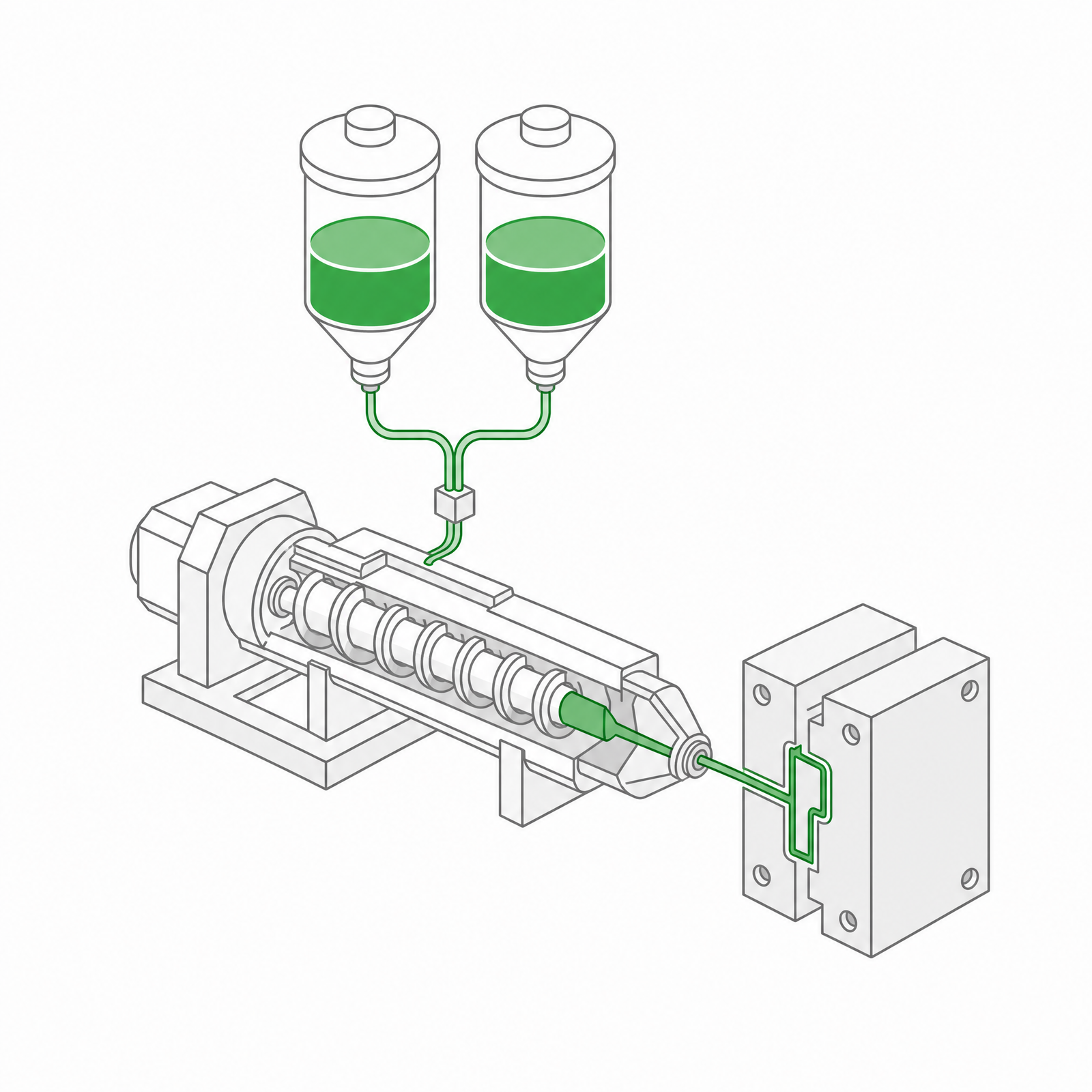 LSR Injection Molding
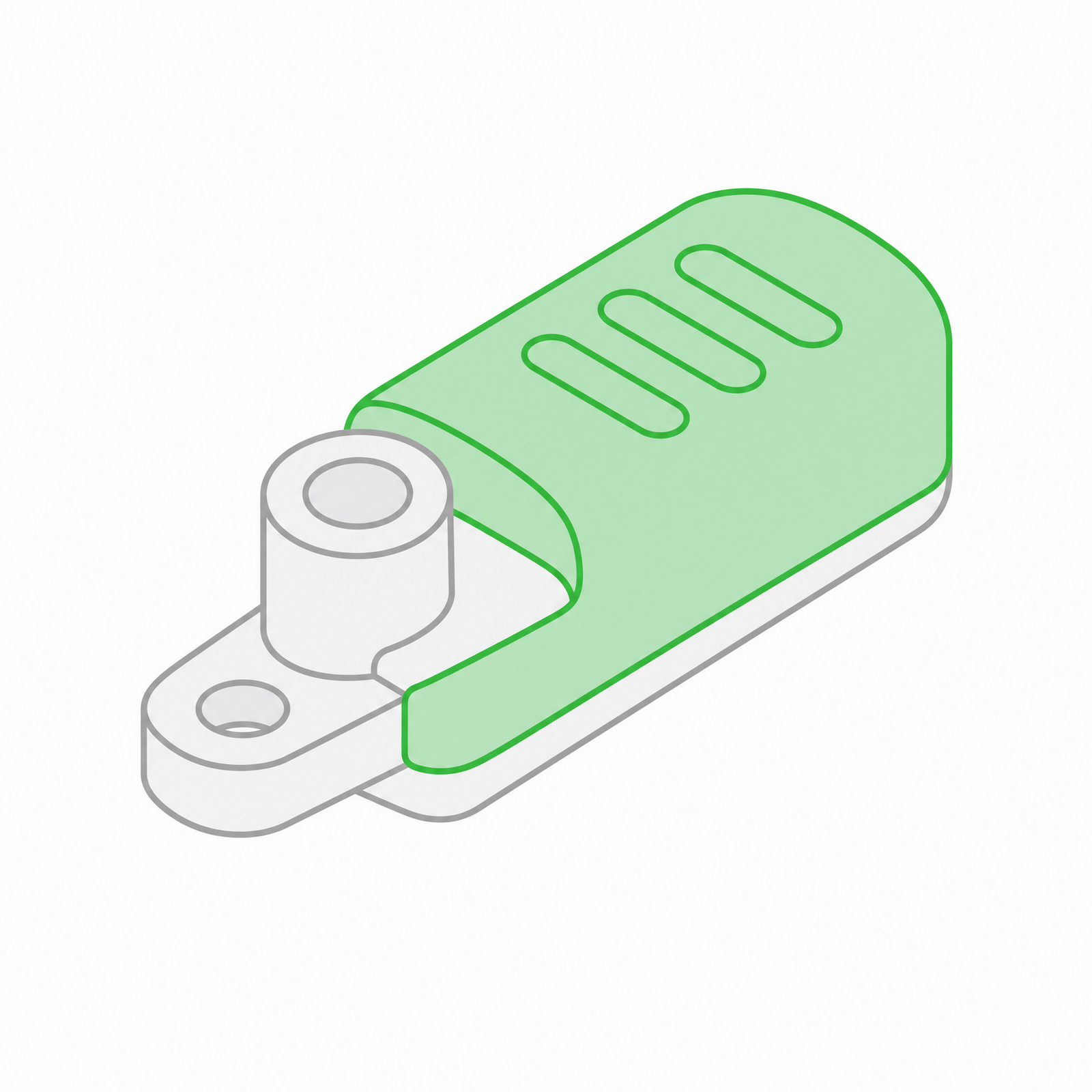 Silicone Rubber Overmolding
 Compression Molding
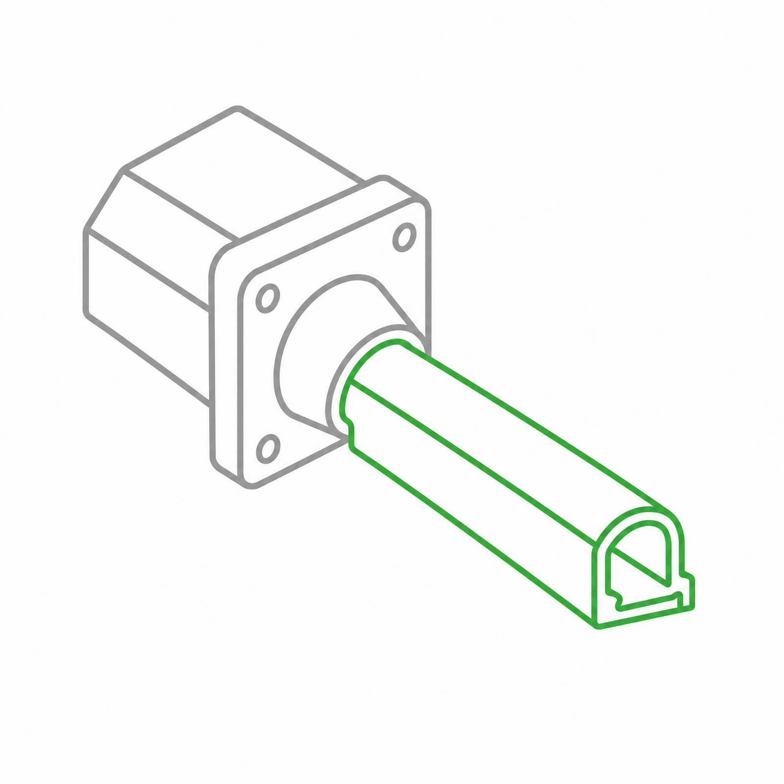 Silicone Rubber Extrusion
 In-house Tooling