
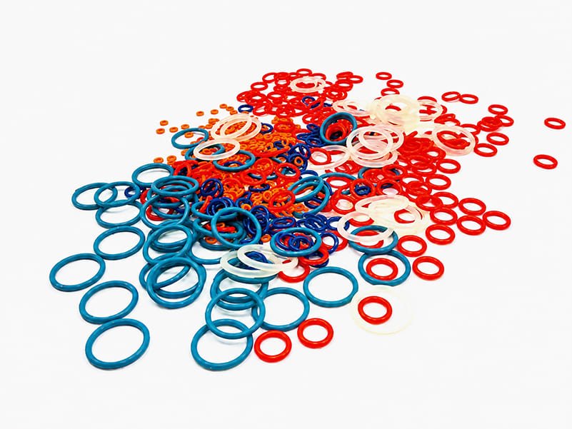
O-rings seal connections in hydraulic systems, pneumatic equipment, vehicles, electronics, and many other assemblies. Their circular cross section deforms inside a groove to close the leakage path between mating surfaces.
When a seal leaks, replacing it with an identical ring may restore operation temporarily. If the fluid, groove, temperature, or assembly method caused the damage, the replacement is likely to fail again. A useful investigation starts with the removed seal and the conditions it experienced.
This guide explains eight common O-ring failure modes, the signs that help distinguish them, and the changes that can prevent recurrence. These checks also help define requirements for custom O-rings when a standard part does not suit the application.
O-Ring Failure Overview
| Failure mode | Typical visible signs | First checks |
|---|---|---|
| Compression set | Flattened cross section with poor recovery | Squeeze, temperature, compound, service time |
| Heat and environmental aging | Hardening, brittleness, surface cracks | Actual seal temperature, ozone, UV, storage |
| Extrusion and nibbling | Ragged or missing material along an edge | Clearance, pressure peaks, hardness, support |
| Abrasion and wear | Worn contact band, scratches, loose particles | Lubrication, surface finish, contamination |
| Chemical degradation | Cracks, discoloration, softening, loss of strength | Fluid identity, concentration, cleaning chemicals |
| Swelling or shrinkage | Changed size, tight fit, looseness, distortion | Fluid absorption, extraction, exposure sequence |
| Temperature or pressure cycling | Intermittent leakage, cracks, blisters, rupture | Cold starts, pressure spikes, depressurization |
| Installation damage | Local cuts, nicks, tears, twisting | Edges, tools, ring size, assembly procedure |
Appearance is a starting point, not a complete diagnosis. A chemically softened ring can also extrude, and excessive friction can produce both abrasion and heat damage. Record where the damage sits relative to the pressure side and moving surface before removing the seal.
1. Compression Set
What it looks like: The cross section remains flattened after removal instead of recovering toward its original round shape. Leakage may develop after cooling, pressure changes, or movement of the joint.
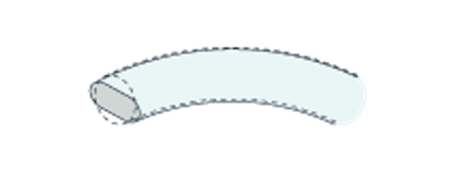
Compression set is residual deformation after compression is released. Long exposure to heat, excessive squeeze, unsuitable material, and inadequate curing can contribute. Some permanent deformation does not automatically mean the seal has failed, but a ring with insufficient recovery may no longer follow changes in the sealing gap.
How to prevent it:
- Select a compound with compression-set data relevant to the operating temperature and exposure time. FKM, HNBR, and silicone grades can be considered where their other properties suit the service.
- Calculate squeeze from the ring cross section and groove dimensions, including tolerances, stretch, and temperature changes.
- Leave appropriate groove volume for thermal expansion and fluid-related swelling.
- Base inspection and replacement intervals on operating conditions and observed seal performance.
A single squeeze range, such as 15–30%, should not be applied to every joint. Static face seals and moving seals have different requirements. Use the appropriate gland recommendations in the O-ring design guide rather than increasing compression until leakage stops.
2. Heat and Environmental Aging
What it looks like: The rubber becomes harder, less flexible, or brittle. Cracks may appear when the removed ring is gently flexed. Surface cracking can also occur after exposure to ozone or weathering.
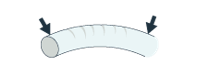
The temperature at the seal may exceed the bulk fluid or ambient temperature. Friction, nearby hot components, and poor heat removal can raise it locally. Ozone and UV exposure introduce additional aging mechanisms, particularly for susceptible compounds or exposed stored parts.
How to prevent it:
- Establish the actual minimum and maximum seal temperatures, including start-up and short excursions.
- Compare compound aging data under the expected fluid and temperature combination.
- Protect stored O-rings from direct sunlight, excessive heat, and ozone-producing equipment.
- Investigate friction or equipment changes if a previously reliable seal starts to overheat.
Material selection still depends on the medium. An elastomer that tolerates hot air may behave differently in hot water, oil, or a cleaning solution. Changing to a heat-resistant material without checking fluid compatibility can exchange one failure mode for another.
3. Extrusion and Nibbling
What it looks like: One edge is ragged, chipped, or partly missing, often on the low-pressure side. Repeated pressure cycling can produce small bites of missing material, commonly called nibbling.
Pressure can push an O-ring into the gap between mating components. If the gap is too large for the pressure and compound, the unsupported rubber becomes damaged. Pressure spikes, component deflection, eccentricity, and chemical softening can worsen the problem.
How to prevent it:
- Check the maximum operating clearance, including manufacturing tolerances and movement under pressure.
- Select hardness and extrusion resistance together with temperature and fluid compatibility.
- Consider correctly sized back-up rings, with support positioned for the pressure direction.
- Investigate pressure spikes and alignment problems instead of relying only on a harder ring.
There is no universal clearance limit of 0.15 mm or minimum hardness of 80 Shore A. Extrusion risk depends on pressure, clearance, compound hardness, temperature, and operating conditions. A tighter groove or harder compound also needs an assembly and sealing-force review.
4. Abrasion and Wear
What it looks like: A worn band, directional scratches, or rubber particles appear at the contact surface. Leakage may increase progressively with operating cycles.
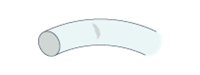
Moving seals encounter friction that stationary joints do not. Insufficient lubrication, abrasive contamination, poor alignment, or an unsuitable mating-surface finish can wear the ring. Excessive squeeze can increase friction and local temperature. Twisting during reciprocating motion can introduce a different, spiral pattern of damage.
How to prevent it:
- Specify a mating-surface finish suitable for the movement and lubricant; simply requesting the smoothest possible surface is not a complete specification.
- Use a lubricant compatible with the elastomer, working fluid, and cleanliness requirements.
- Control particles, burrs, side loading, and misalignment.
- Evaluate wear-resistant compounds or a different seal profile when the motion is unsuitable for an O-ring.
PU and HNBR compounds may be candidates for selected dynamic duties, but they still require fluid and temperature checks. General-purpose silicone should not be selected for sliding wear solely because it remains flexible. The distinction between static and dynamic seals helps establish the correct design priorities.
5. Chemical Degradation
What it looks like: The ring develops cracks, discoloration, tackiness, softening, or a loss of strength. A seal may look relatively intact but tear unusually easily during removal.
Chemical degradation occurs when the environment damages the material itself. The working fluid is only one possible source. Cleaning agents, assembly lubricants, additives, and residues may expose the seal to a different chemical environment than the specification originally assumed.
How to prevent it:
- Record the full fluid identity, concentration, temperature, and exposure duration.
- Include cleaning, flushing, and assembly chemicals in the compatibility review.
- Screen exact compounds using supplier data, then evaluate samples under representative conditions.
- Examine changes in hardness, dimensions, and mechanical condition alongside leakage results.
FKM, FFKM, and EPDM are not interchangeable solutions for every chemical. For example, conventional FKM is generally unsuitable for many ketones, while EPDM is generally unsuitable for petroleum oils. These exceptions illustrate why a material family name alone is insufficient. Review the actual grade and exposure conditions before approving a substitution.
6. Swelling and Shrinkage
What it looks like: A ring becomes oversized, distorted, difficult to remove, or unexpectedly loose. Swelling may increase groove fill and friction; shrinkage can reduce squeeze and allow leakage.
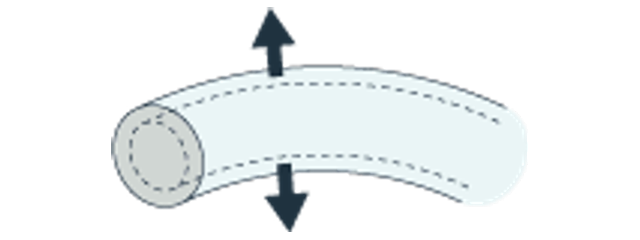
An elastomer may absorb fluid without immediately showing the cracking associated with chemical degradation. Fluids can also extract ingredients from a compound. Subsequent drying or changes between process and cleaning fluids can reveal further dimensional changes. Swelling and chemical degradation may occur together, but they should be assessed separately.
How to prevent it:
- Evaluate volume change using the actual fluid and a representative temperature and duration.
- Measure hardness and dimensions before and after exposure, including recovery after drying where relevant.
- Allow for validated volume change in groove-fill calculations.
- Investigate the complete exposure sequence when a seal changes size after cleaning or shutdown.
Do not assume that FKM or FFKM has low absorption in every liquid. PTFE may offer useful chemical resistance, but its low elasticity requires a different design and installation review from an elastomer O-ring. It should not be specified as a direct replacement without checking the sealing arrangement.
7. Temperature and Pressure Cycling
What it looks like: Leakage appears during cold starts or pressure changes. More severe cases can show cracks, blisters, or ruptures after depressurization.
These symptoms can arise through different mechanisms. At low temperature, an elastomer can lose the flexibility needed to follow the joint. A pressure spike can increase extrusion risk. In high-pressure gas service, absorbed gas can expand inside the rubber when the system depressurizes too quickly, causing rapid gas decompression damage.
How to prevent it:
- Evaluate the exact compound at the cold-start temperature as well as the maximum operating temperature.
- Record pressure peaks, cycling frequency, gas composition, and the depressurization sequence.
- For relevant gas duties, consider compounds qualified for rapid gas decompression under applicable service conditions.
- Control pressure changes through the equipment’s approved operating procedure and verify performance through representative cycling.
FKM or HNBR should not be selected for all temperature transitions by default. Low-temperature capability and decompression resistance depend on the specific compound and test conditions.
8. Installation Damage
What it looks like: A new seal leaks immediately or fails early. Inspection reveals a localized cut, nick, tear, pinched area, or twisted section rather than uniform aging or wear.
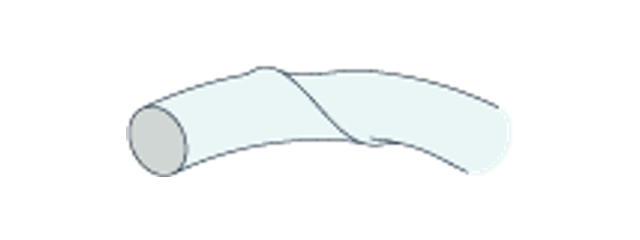
Threads, sharp edges, burrs, unsuitable tools, and excessive stretching can damage an otherwise appropriate ring. An incorrect size may also make installation difficult or leave the seal displaced in the groove. A damaged ring can sometimes pass an initial leak check before the defect grows in service.
How to prevent it:
- Clean and inspect the groove, lead-in chamfer, and mating parts before assembly.
- Cover exposed threads or sharp features with an appropriate installation sleeve.
- Use suitable non-damaging tools and controlled stretching within the supplier’s installation limits.
- Apply an approved compatible lubricant when the application permits it.
- Confirm that the ring is seated evenly without twisting, pinching, or trapped contamination.
O-rings can be installed by hand where appropriate; the important distinction is controlled handling versus uncontrolled stretching or contact with sharp features. Replace a visibly damaged ring rather than forcing it into the assembly.
Failed O-Ring Inspection Checklist
Keep the failed seal, identify its installed orientation, and compare it with an unused ring of the same specification. Photographs and operating records are more useful than a description such as “the rubber broke.”
Prepare the following information for a material and manufacturing review:
- Seal and groove dimensions: inside diameter, cross section, groove drawing, tolerances, and mating clearance.
- Exposure: working fluid, concentration, cleaning agents, lubricant, and temperature range.
- Loading and movement: operating pressure, pressure peaks, static or dynamic duty, speed, and cycle history.
- Failure evidence: location of damage, time in service, leakage conditions, and any change in size or hardness.
- Replacement requirements: material identification, inspection criteria, expected quantity, and documentation needs.
For equipment with patient-contact, drug-contact, or sterilization requirements, the review also needs the relevant material and validation inputs. Our medical O-ring manufacturing page explains those project considerations.
Fecision can review custom O-ring geometry, material requirements, tooling, and molding feasibility against the supplied operating conditions. The approved replacement should then be verified in the actual assembly so that correcting one failure mode does not introduce another.
 LSR Injection Molding
 Silicone Rubber Overmolding
 Compression Molding
 Silicone Rubber Extrusion
 In-house Tooling