
LSR tooling is different from tooling for thermoplastics or high-consistency rubber. Liquid silicone rubber has very low viscosity, fills cavities quickly, cures in a hot mold, and can flash through extremely small gaps. A successful LSR mold therefore depends on details that may look secondary in a CAD review: where the air escapes, how the parting line seals, how the gate is thermally isolated, and how the cured silicone releases from steel.
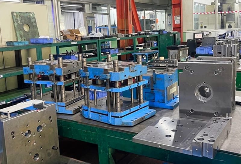
LSR tooling needs to be developed with the part and process. Cavity dimensions must allow for shrinkage, and the mold needs balanced heating and a way for air to escape. A workable release method then lets the cured part leave the tool without damage.
Why LSR Tooling Needs Different Thinking
LSR generally flows easily, even at relatively low injection pressure. That helps it fill thin walls, small ribs, and detailed sealing features, but it also creates two tooling challenges.
First, air has less time to escape. If air remains in the cavity, the part may show voids, burn marks, incomplete fill, weak knit areas, or pale edges where the silicone fails to pack correctly.
Second, LSR can flash more easily than many plastics. The parting line, ejector system, shutoffs, and insert interfaces must be built with high precision. A small clearance that would be acceptable for a thermoplastic part may create silicone flash.
LSR also behaves differently during temperature change. In the hot mold, it does not simply shrink like a thermoplastic melt. It tends to expand under heat and then contract after demolding and cooling. Because of this behavior, the molded part does not always stay on the expected core side. It may remain in the cavity half with the larger contact area unless draft, surface finish, venting, and ejection are planned carefully.
Shrinkage
LSR shrinkage after demolding and cooling is often estimated at around 2.5% to 3.0%. The actual value depends on the compound and how heat reaches the part during curing. Demolding temperature and any post-cure cycle also affect the result, so published values should be checked through sampling before finalizing the tool.
Several tooling-related factors influence the apparent shrinkage of an LSR part:
- Mold temperature and temperature uniformity.
- Part temperature at the moment of demolding.
- Pressure in the cavity during packing and cure.
- Compression of the material during cure.
- Gate location and flow direction.
- Wall thickness and overall part geometry.
- Post-cure, when required by the application.
Shrinkage is often direction-dependent. The shrinkage along the flow direction can be different from the shrinkage perpendicular to the flow direction. Thick sections may also shrink differently from thin sections. For parts with sealing lips, optical features, or assembly-critical dimensions, this means the first tooling review should separate functional dimensions from non-critical dimensions.
Use the drawing to identify the dimensions that must be protected, then align the gate position, flow path, and inspection plan around those dimensions. For tolerance planning, see our silicone rubber tolerance guide.
Parting Line
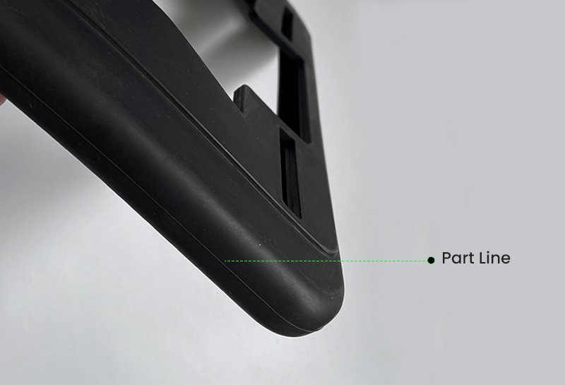
Parting line selection is one of the first decisions in LSR mold design. Because LSR has low viscosity, the parting line must seal accurately to control flash. At the same time, the parting line affects visible appearance, demolding direction, vent placement, and how the part locates in the mold.
A practical parting line review should answer four questions:
- Will the parting line leave flash on a sealing surface, cosmetic surface, or assembly surface?
- Can the part release cleanly from the intended side of the mold?
- Can the final fill area be vented without damaging the function of the part?
- Can shutoffs, slides, inserts, and ejector features be sealed tightly enough for LSR?
Adding small chamfers or radii can help the part locate and release more consistently. For flexible silicone rubber parts, geometry often controls release more than simple draft angle alone. If one half of the mold has much more surface contact than the other, the cured part may prefer that side even when the designer expected it to remain on the core.
For tight flash requirements, avoid placing the parting line across functional sealing edges wherever possible. When that cannot be avoided, define the allowable flash direction and trimming strategy before steel is cut.
Venting
Venting is one of the most important features in LSR tooling. As LSR enters the cavity, trapped air is compressed. If the air cannot leave through a vent, it remains in the silicone or prevents complete filling.
Vents are usually placed on the parting line at the area reached last by the material flow. This placement gives the displaced air a path out of the cavity and helps reduce bubbles, weak bonding areas, and incomplete fill.
Common vent dimensions are very shallow. As a practical starting point, vent channels may be about 1 to 3 mm wide and about 0.004 to 0.005 mm deep, then adjusted based on material, tool construction, and flash tolerance. The exact depth must be validated because LSR can flash through a vent that is too deep, while a vent that is too shallow may clog or fail to evacuate air.
Vacuum Assist for Difficult LSR Parts
Vacuum-assisted tooling can provide the best venting performance for complex parts, large parts, thin-wall parts, and multi-cavity production. A vacuum system is typically created by sealing around the parting line and pulling vacuum from the cavities before injection.
The basic sequence is:
- The mold closes to a controlled position.
- The cavity area is evacuated through the vacuum system.
- Once the target vacuum level is reached, the mold closes fully.
- Injection begins and LSR fills the cavity with less trapped air.
Some LSR injection molding equipment allows variable clamping force. In this process, the mold can close at a lower force while the cavity is partially filled, allowing air to escape more easily. When the cavity is about 90% to 95% full, the machine switches to a higher clamping force to prevent silicone expansion from creating flash.
Vacuum is not a substitute for good vent design. It works best when parting line seals, vent locations, runner balance, and mold maintenance are all controlled.
Gate and Runner Design
For LSR injection molding, a cold runner system is often preferred because it reduces material waste and improves production efficiency. Since LSR cures in a hot mold, the runner must stay cool enough to prevent premature cure before the material reaches the cavity.
A cold runner can also eliminate the need to remove a cured sprue or runner from every shot. This reduces labor, shortens cycle time, and avoids unnecessary material loss, especially in high-volume multi-cavity molds.
Needle valve nozzles are commonly used for positive flow control. Pneumatically actuated valve gates can be positioned at multiple locations in the mold, allowing the tool designer to fill complex or multi-cavity parts more evenly.
In compact tools, open cold runner systems may allow several injection points within a limited mold area. This can help fill many small LSR components without creating large runner waste or extra degating work.
Thermal Isolation
Cold runner tooling only works when the hot cavity and cold runner are thermally separated. If the runner becomes too hot, the LSR may begin to cure before injection. If the gate region is cooled too aggressively, the material may absorb too much heat from the cavity entrance and fail to cure completely near the gate.
Thermal control should be reviewed around:
- The nozzle seat.
- Gate inserts.
- Insulating plates.
- Cooling circuits or cold runner temperature control.
- Heater location near the cavity.
- The distance between the heated cavity and the cold runner.
Conventional Runner and Gate Options
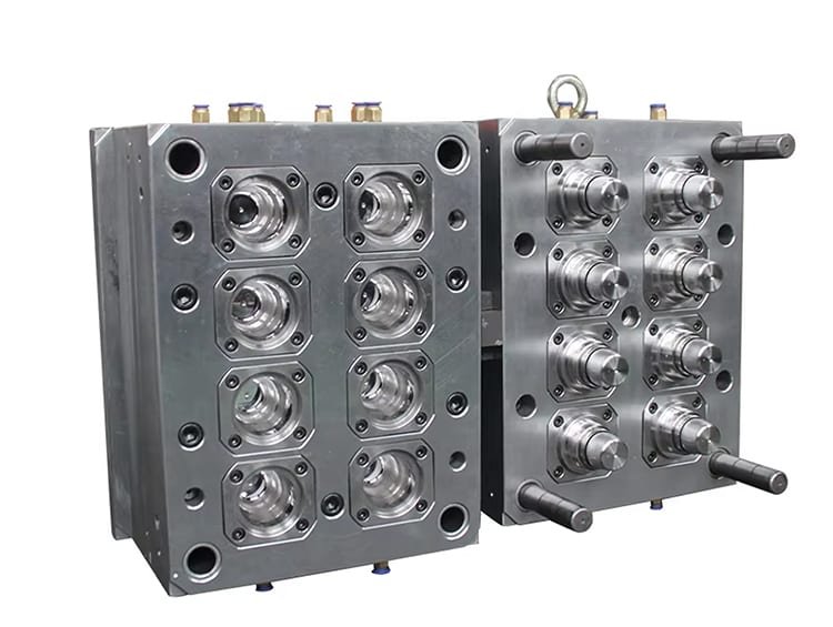
When a conventional runner is used, small gate diameters are common. For sub gates or tapered gates, a gate diameter of about 0.2 to 0.5 mm may be used as an initial reference, depending on part size, material viscosity, cavity count, and cosmetic requirements.
Because LSR is low viscosity, runner balance matters. In a multi-cavity mold, each cavity should receive material at the same pressure and timing. Flow simulation and short-shot trials are useful for confirming whether all cavities fill evenly.
Demolding
Cured LSR can adhere to metal surfaces, and its flexibility can make demolding more difficult than expected. The good news is that LSR normally has enough hot tear strength to release without damage when the tool is designed correctly.
Common LSR demolding systems include:
- Stripper plate ejection.
- Ejector pin ejection.
- Air-assisted demolding.
- Roller stripping.
- Take-off plate demolding.
The right system depends on part geometry. A soft gasket, a long lip seal, and a thick overmolded component may all need different release strategies.
For ejector systems, precision matters. Excessive clearance between ejector pins and guide sleeves can become a flash path. Wear over long production runs can create the same problem. For this reason, ejector clearances, pin materials, and maintenance intervals should be reviewed as part of the tooling plan.
Tapered or mushroom-shaped ejector pins can help improve sealing because they allow a larger contact pressure at the shutoff area. They are especially useful when a normal straight pin would increase the risk of flash.
Mold Steel and Surface Finish
Mold material selection affects dimensional stability, wear resistance, surface finish, and maintenance cost. For LSR tooling, the cavity material must tolerate elevated mold temperature, repeated clamping, and in some cases abrasive or highly filled silicone compounds.
Common considerations include:
- Mold base and support plates may use non-alloy tool steel such as C45W or equivalent grades.
- For hot plates around 210 C and impact-sensitive service, pre-hardened steels such as 1.2312 or equivalent grades may be considered.
- Cavity plates are commonly made from nitrided, tempered, or otherwise heat-treated mold steels.
- For highly filled or oil-resistant LSR grades, harder materials, bright chrome-plated steel, or powder-metallurgy steels such as 1.2379 or equivalent grades may improve wear resistance.
- High-wear areas should be designed as replaceable inserts where practical.
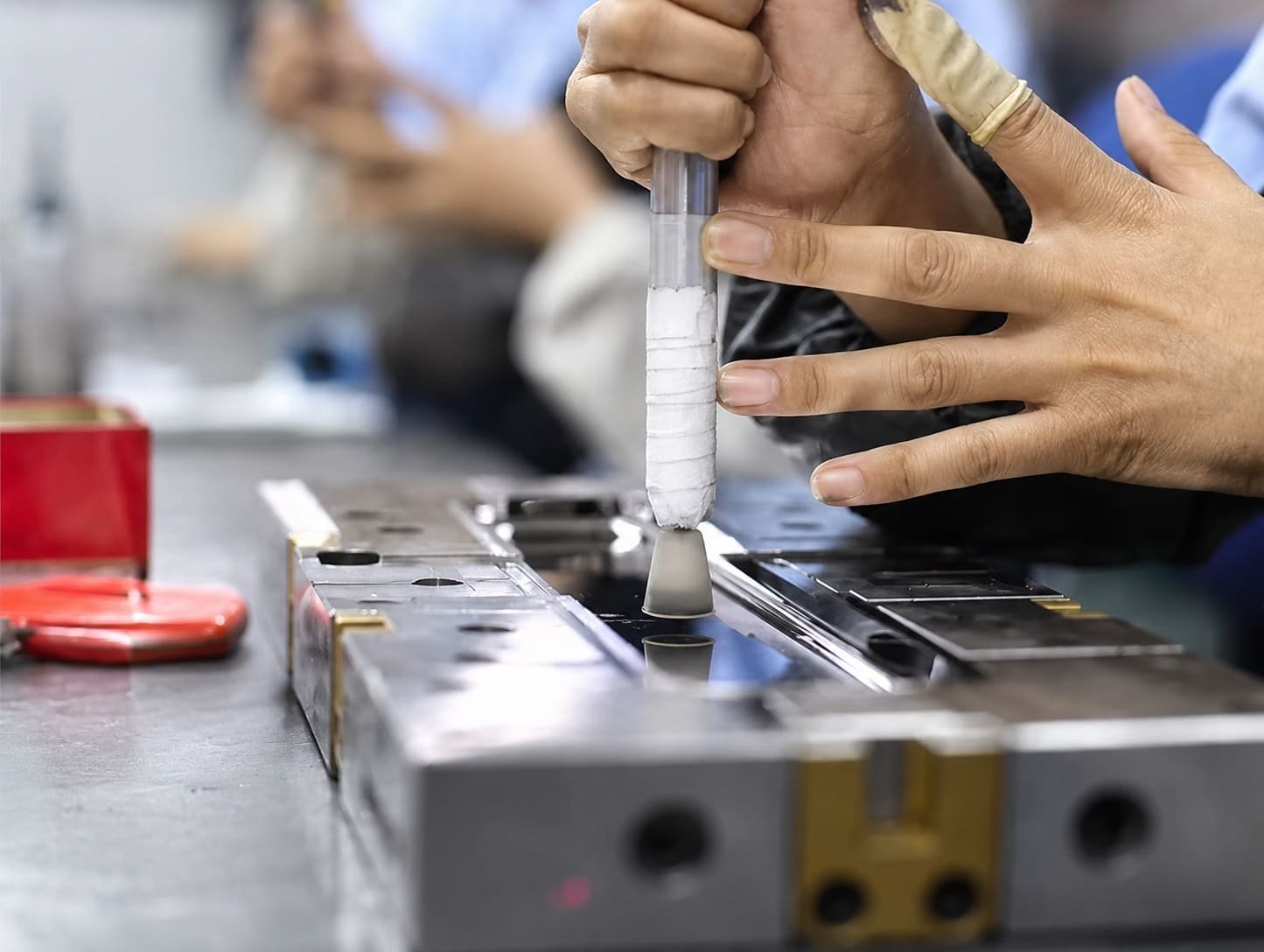
Surface finish directly transfers to the molded part. A transparent LSR part usually requires polished steel. A matte medical component, grip surface, or sealing surface may need a different finish. Surface coatings can also be used: titanium/nickel treatments can improve wear resistance, while PTFE/nickel coatings can improve release.
Choose the surface finish for the function, not only for appearance. A sealing surface may require a different finish than a cosmetic grip area. A release-friendly texture may help demolding but may also change the look or friction of the finished part.
Temperature Control
LSR cures in a heated mold, so temperature control is central to cycle time and part quality. Electric heating is common, using cartridge heaters, strip heaters, or heating plates. For large molds, oil temperature control can be a practical and economical way to improve thermal uniformity.
The goal is not only to reach the target temperature. The goal is to keep the whole cavity area uniform enough that the LSR cures consistently.
Poor temperature control can cause:
- Slow cure and difficult demolding.
- Uneven shrinkage.
- Incomplete cure near gates or thick sections.
- Excessive flash caused by plate distortion.
- Cycle-to-cycle dimensional variation.
- Surface defects from local hot or cold areas.
Insulating plates can reduce heat loss between the mold and support plates. Heater placement also matters. If heaters are too close to the parting line, they may cause plate bending or thermal distortion, which can create flash on the molded part.
For molds with cold runners, the hot side and cold side must be separated clearly. Thermal isolation is not an optional detail. It is part of the process window.
LSR Tooling Failure Modes
| Tooling Issue | Likely Cause | How to Prevent |
|---|---|---|
| Flash at parting line | Low-viscosity LSR entering small gaps, poor shutoff, plate distortion, or worn ejector features | Improve parting line precision, review clamp force, control heater placement, maintain ejector clearances |
| Bubbles or pale edges | Trapped air or insufficient venting | Place vents at last-fill areas, use vacuum assist where needed, validate with short-shot trials |
| Incomplete cure near gate | Poor thermal separation or gate region too cold | Balance cold runner cooling with hot cavity temperature, review gate insert design |
| Premature cure in runner | Runner temperature too high | Improve cold runner temperature control and thermal isolation |
| Part sticks in wrong mold half | Contact area, surface finish, or geometry favors the cavity side | Adjust draft, texture, release strategy, ejection, and parting line position |
| Tearing during release | Insufficient release support or high adhesion to steel | Add air assist, stripper plates, release-friendly coating, or demolding-friendly geometry |
| Uneven dimensions across cavities | Imbalanced runner system or uneven temperature | Use balanced runner design, flow simulation, temperature mapping, and cavity-by-cavity inspection |
When to Use In-House Tooling Support
Keep part designers and mold engineers involved during trial molding. When inspection finds a problem, an in-house tooling team can relate it to the tool and make a correction. This makes sampling feedback easier to apply before production release.
For many custom silicone rubber programs, the tooling strategy is simple: make the mold precise enough to control flash, vented enough to remove air, thermally stable enough to cure consistently, and practical enough to demold every shot without damage. When those basics are handled well, LSR injection molding can deliver clean, repeatable, high-volume silicone rubber parts.
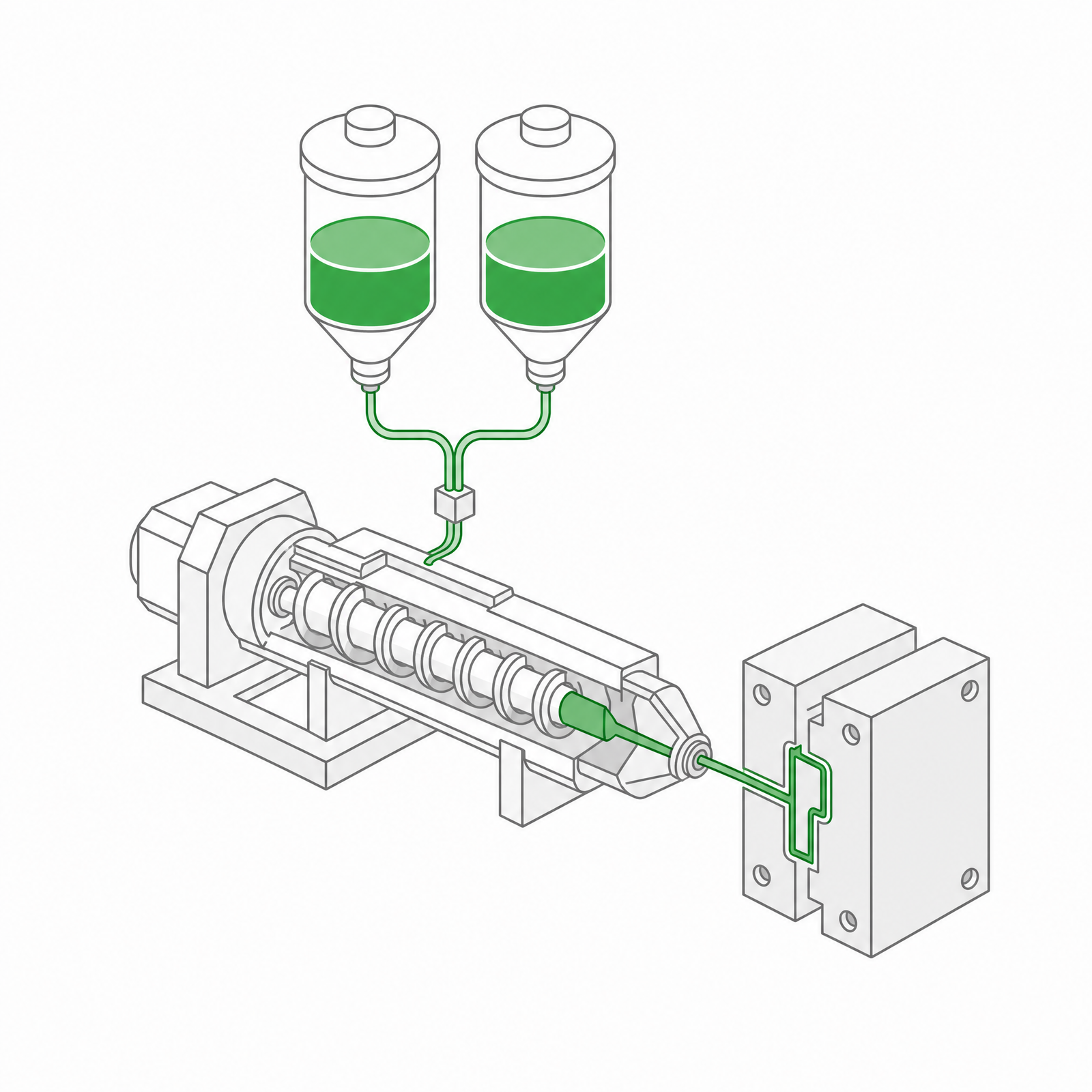 LSR Injection Molding
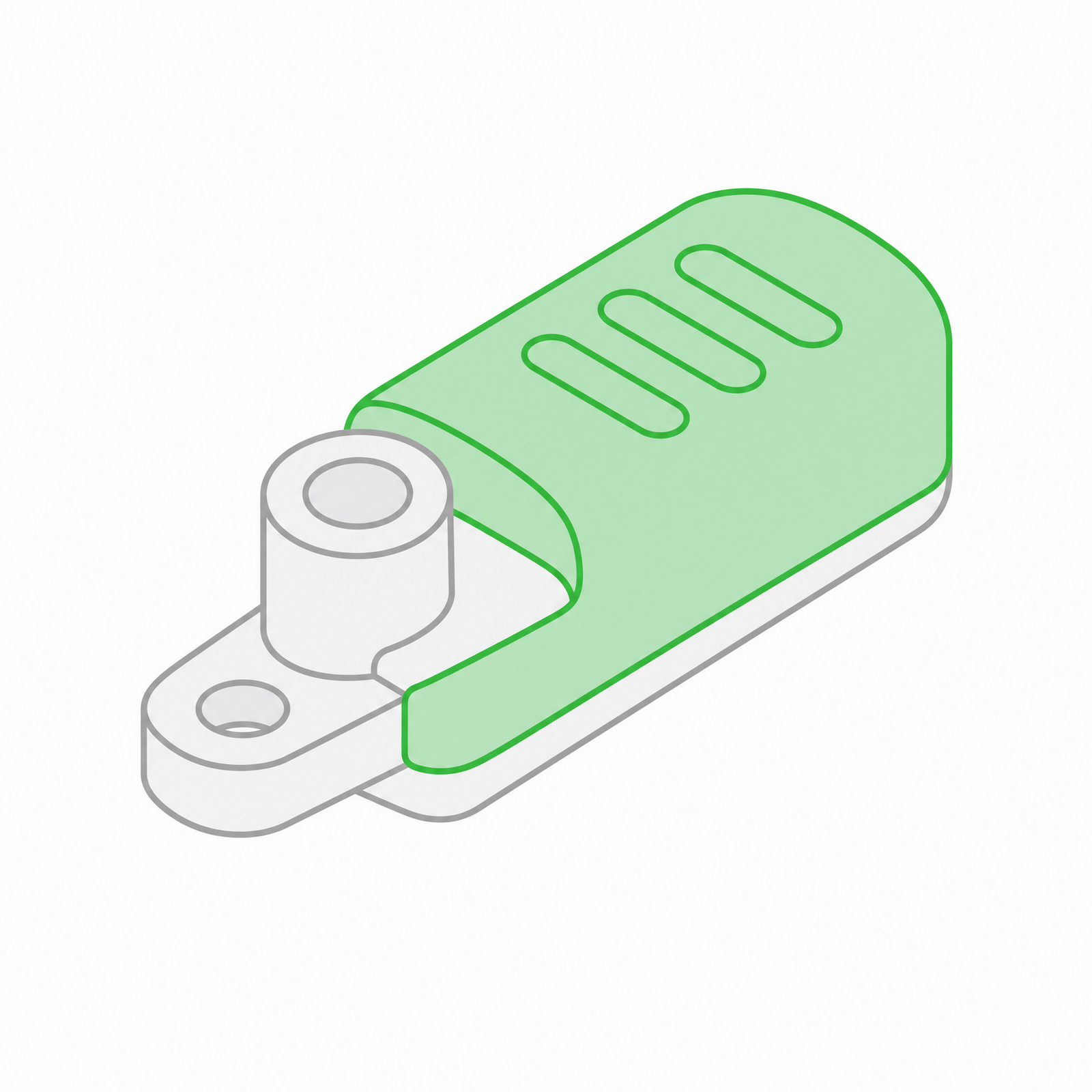 Silicone Rubber Overmolding
 Compression Molding
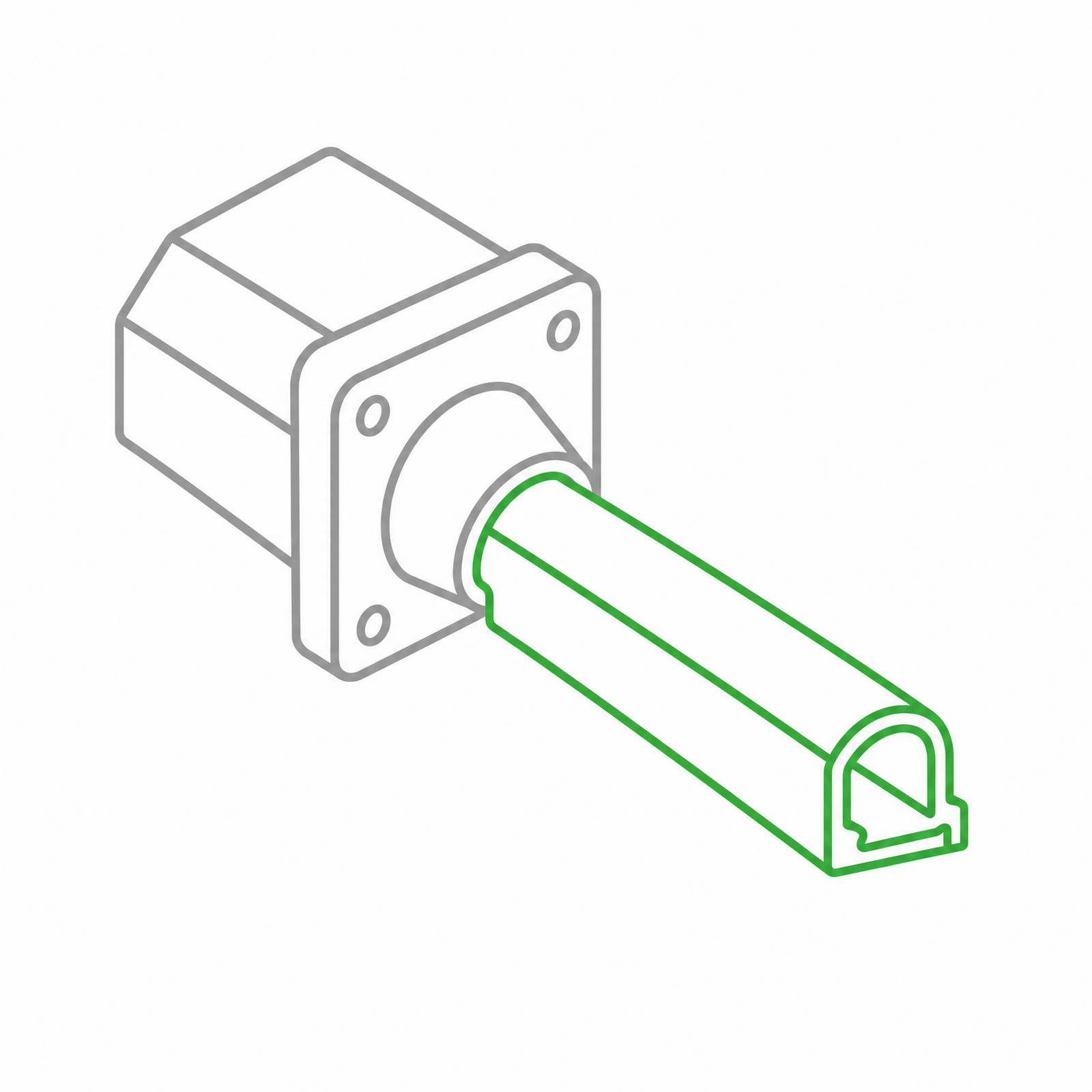 Silicone Rubber Extrusion
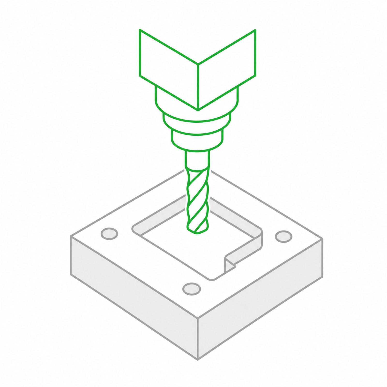 In-house Tooling