
What Is an O-Ring?
An O-ring is a rubber sealing ring with a circular cross section, its name comes directly from its “O” shape. O-rings first appeared in the mid-19th century, where they were used to seal steam engine cylinders. Thanks to their low cost, simple manufacturing, reliable performance, and easy installation, O-rings have become the most common sealing element in mechanical design. They can withstand pressures of tens of megapascals (thousands of psi) and work in both static applications and dynamic applications where parts move relative to each other, such as rotary pump shafts and hydraulic cylinder pistons.
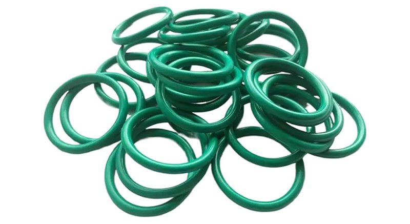
Features of O-Rings
An O-ring is a compact, ring-shaped sealing element, most often with a round cross section and made from synthetic rubber. It is the most widely used seal in hydraulic engineering, serving mainly in static and sliding (dynamic) sealing applications. Compared with other sealing elements, O-rings offer the following advantages:
- Excellent sealing performance and long service life.
- A single ring seals in both directions.
- Good adaptability to oil, temperature, and pressure.
- Low dynamic friction.
- Small size, light weight, and low cost.
- Simple gland design; easy to install and remove.
- Suitable for both static and dynamic sealing.
- Ring sizes and gland dimensions are standardized, making selection and sourcing easy.
On the downside, O-rings exhibit higher breakout friction at the start of dynamic movement — roughly 3 to 4 times the running friction — and under high pressure they can be forced (extruded) into the clearance gap.
How Do O-Rings Seal?
Static Sealing
An O-ring is a compression-type seal. Its working principle is straightforward: the ring deforms elastically when installed, generating contact pressure on the sealing surfaces. As long as this contact pressure exceeds the internal pressure of the sealed medium, no leakage occurs; otherwise, the seal leaks. The process by which the medium’s own pressure further energizes the O-ring and improves the seal is known as the “self-energizing effect.”
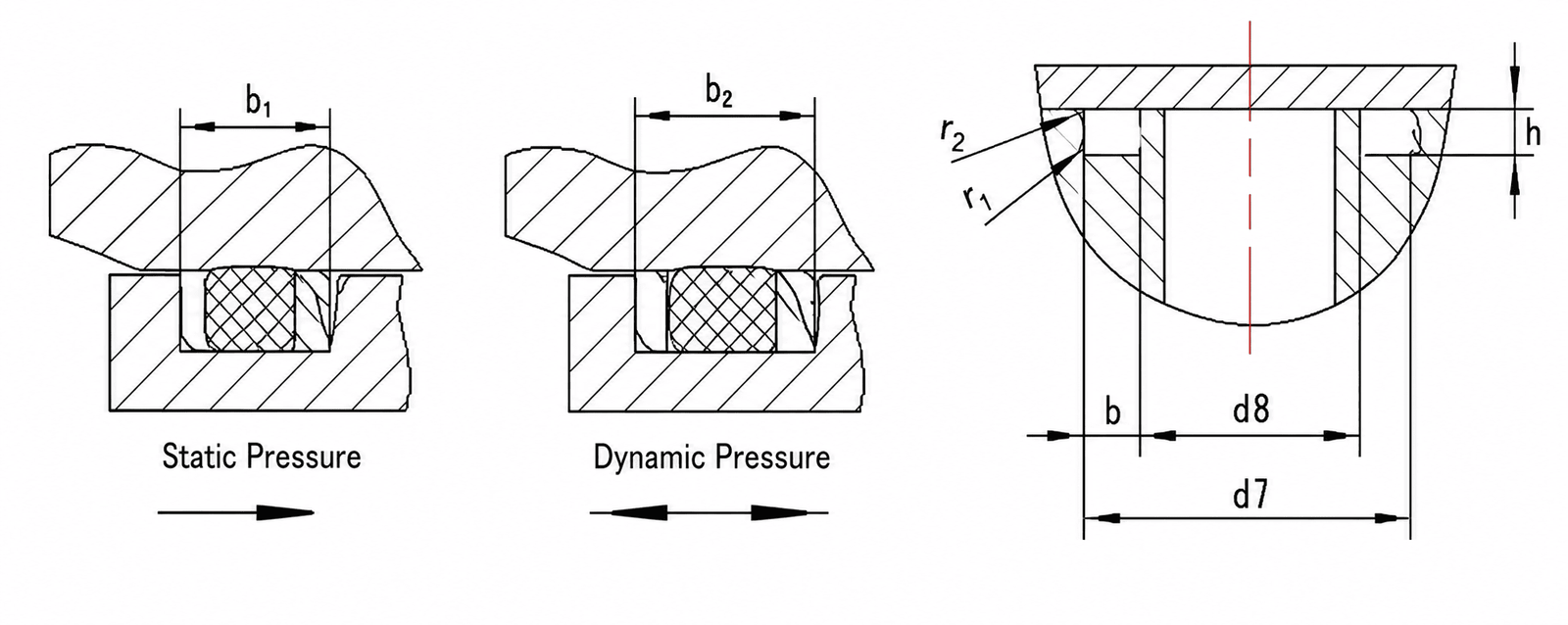
Because of the initial preload, the O-ring sits in tight contact with both the mating surface and the bottom of the gland. When fluid enters the gland through the clearance, it can only act on one side of the ring. As fluid pressure rises, the O-ring is pushed against the opposite side of the gland and deforms into a “D” shape, transferring the pressure to the contact surface.
Self-energization has its limits. When internal pressure becomes too high, “extrusion” occurs: with a clearance gap present at the sealing interface, the pressurized O-ring experiences stress concentration at the gap. Once the stress exceeds what the rubber compound can withstand, material is forced out through the gap. At that point the O-ring may still appear to hold the seal temporarily, but it is already damaged — which is why proper selection matters.
Dynamic Sealing
In dynamic applications, the preload and self-energizing behavior of an O-ring are the same as in static sealing. The situation is more complex, however, because a moving rod tends to drag fluid into the interface between the O-ring and the rod.
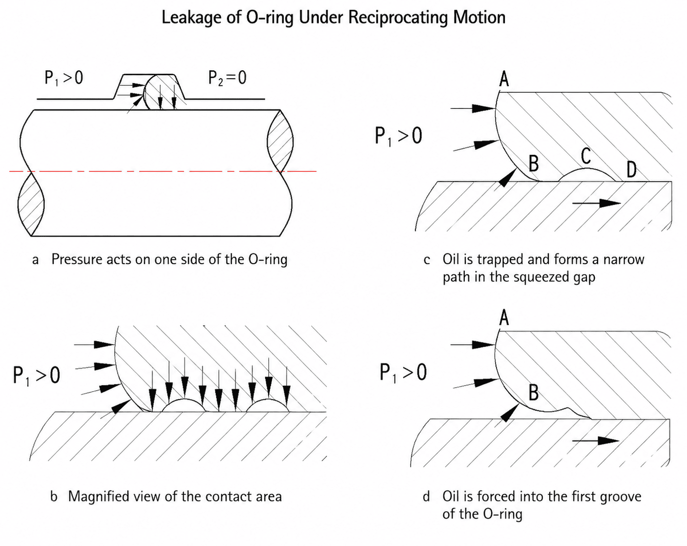
Consider an O-ring with system pressure P₁ acting on its left side. If you magnify the contact zone between the ring and the rod, the surfaces are actually microscopically rough — not every point touches the metal. Thanks to self-energization, the contact pressure the O-ring exerts on the rod exceeds P₁, so the seal holds. But as the rod begins moving to the right, the fluid film clinging to the rod is dragged into the wedge-shaped gap. Hydrodynamic effects raise the pressure of this trapped film above P₁; once it exceeds the O-ring’s contact pressure on the rod, fluid is forced into the first microscopic pocket of the contact surface. As the rod keeps moving, fluid works its way from one pocket to the next, eventually leaking along the direction of rod travel. When the rod moves back to the left, the drag direction opposes the pressure direction, so leakage is far less likely. Leakage rate increases with fluid viscosity and rod speed, and is also closely related to O-ring size and working pressure.
O-Ring Design Guide
Compression (Squeeze)
The compression ratio W is calculated as: W = (d₂ − h) / d₂ × 100%
Where:
- d₂ — the O-ring’s cross-sectional diameter in the free state (mm)
- h — the distance from the gland bottom to the mating surface (gland depth), i.e., the installed height of the compressed O-ring (mm)
When selecting a compression ratio, keep three things in mind:
- Maintain adequate sealing contact area.
- Keep friction as low as possible.
- Avoid permanent (compression) set.
The right compression ratio depends on the application — static or dynamic. Static seals are further divided into radial and face (axial) seals: radial seals close off a radial clearance, while face seals close off an axial clearance. Face seals are also split into two cases depending on whether pressure acts on the ring’s ID or OD; internal pressure adds stretch to the ring, while external pressure reduces its initial stretch. Because the medium acts on the O-ring differently in each configuration, the preload design differs accordingly. For dynamic seals, you need to distinguish between reciprocating and rotary motion.
Static seals: Cylindrical static seals follow the same practice as reciprocating seals — generally W = 10%–15%. For face (flange) static seals, use W = 15%–30%.
Dynamic seals: fall into three cases:
Reciprocating motion generally uses W = 10%–15%. For rotary seals, the Joule (Gough–Joule) heating effect must be considered when choosing compression.
For rotary service, the O-ring’s ID should be 3%–5% larger than the shaft diameter, with an OD compression of W = 3%–8%.
For low-friction designs, a smaller compression ratio is chosen to reduce drag — typically W = 5%–8%. You should also account for rubber swelling caused by the medium and by temperature. Beyond the designed compression set, a maximum swell of 15% is generally acceptable; anything beyond that means the material is wrong for the application — switch to a different compound or adjust the compression ratio accordingly.
Stretch
Once installed in a gland, an O-ring is almost always under some amount of stretch. Like compression, stretch has a major influence on sealing performance and service life. Too much stretch not only makes installation difficult, but also reduces the effective cross-section d₂, lowering the actual compression and inviting leakage. Stretch α is calculated as: α = (d + d₂) / (d₁ + d₂)
Where: d — shaft diameter (mm); d₁ — O-ring inside diameter (mm).
Recommended stretch falls between 1% and 5%. The table below lists recommended values; select the stretch based on shaft diameter.
Table 1 — Recommended Ranges for O-Ring Compression and Stretch
| Sealing Type | Medium | Stretch α (%) | Compression w (%) |
|---|---|---|---|
| Static | Hydraulic oil | 1.03–1.04 | 15–25 |
| Static | Air | <1.01 | 15–25 |
| Reciprocating | Hydraulic oil | 1.02 | 12–17 |
| Reciprocating | Air | <1.01 | 12–17 |
| Rotary | Hydraulic oil | 0.95–1 | 3–8 |
Gland (Groove) Design
The actual compression applied to an O-ring is determined by the geometry and dimensions of the gland. Rectangular and triangular grooves are the common shapes; triangular grooves are generally reserved for certain static seals. Because required compression differs, glands for static, reciprocating, and rotary seals may look similar but differ in dimensions.
Groove Width
Groove width is governed by three considerations:
- It must exceed the O-ring’s maximum diameter after compression.
- It must allow for thermal expansion from frictional heating during motion, plus volume swell from the medium.
- In reciprocating service, the groove must leave enough room for the ring to roll freely. As a rule of thumb, the O-ring’s cross-sectional area should occupy no more than 85% of the rectangular groove area, and groove width is commonly taken as 1.5 times the O-ring’s cross-sectional diameter.
Note: A groove that is too narrow increases friction during motion and accelerates wear. A groove that is too wide gives the ring too much room to wander, which also causes wear — and under pulsating pressure in static service, the ring can oscillate and abrade abnormally. In addition, at high internal pressures a backup ring is mandatory, and the groove width must be increased accordingly.
Groove Depth
Groove depth is the critical dimension for proper O-ring function, as it directly sets the compression. The deformation consists of the compression at the ring’s ID (δ₁) and at its OD (δ₂). When δ₁ = δ₂, the center of the O-ring cross section coincides with the center of the groove — the circumferences match and the ring is installed without stretch. When δ₁ > δ₂, the ring’s center-line circumference is shorter than the groove’s, meaning the ring sits in the groove under tension (stretch). When δ₁ < δ₂, the ring’s circumference exceeds the groove’s, so the ring works in circumferential compression and may “pop out” during disassembly. When designing groove depth, first determine how the O-ring will be used, then select an appropriate compression ratio (see Table 1).
Beyond that, material-related factors such as swelling in the medium and the compound’s own thermal expansion must also be considered — gland design involves many variables. National standards for gland geometry have been published for reference.
Groove Selection and Design
Gland Configurations
Common configurations include radial glands with backup rings and face (axial) glands.
Notes:
- As a general rule, to prevent the O-ring from being damaged by extrusion into the clearance, backup rings should be added when fluid working pressure exceeds 10 MPa; for static seals, when pressure exceeds 32 MPa (see Fig. c). The number of backup rings depends on how the ring is loaded.
- For face seals with external pressure, add a shoulder at diameter d8 to keep the O-ring from migrating into the bore.
Gland dimension series have been standardized in China; see Tables 2 and 3.
Table 2 — Radial Gland Dimensions for O-Rings
| Item | Detail | d₂ = 1.80 | 2.65 | 3.55 | 5.30 | 7.00 |
|---|---|---|---|---|---|---|
| Groove width | Pneumatic | 2.2 | 3.4 | 4.6 | 6.9 | 9.3 |
| Groove width (hydraulic dynamic or static) | b⁺⁰·²⁵ | 2.4 | 3.6 | 4.8 | 7.1 | 9.5 |
| Same as above | b₁⁺⁰·²⁵ | 3.8 | 5.0 | 6.2 | 9.0 | 12.3 |
| Same as above | b₂⁺⁰·²⁵ | 5.2 | 6.4 | 7.6 | 10.9 | 15.1 |
| Groove depth t (piston seal, for d₃) | Hydraulic dynamic | 1.42 | 2.16 | 2.96 | 4.48 | 5.95 |
| Same as above | Pneumatic dynamic | 1.46 | 2.23 | 3.03 | 4.65 | 6.20 |
| Same as above | Static | 1.38 | 2.07 | 2.74 | 4.19 | 5.67 |
| Groove depth t (rod seal, for d₆) | Hydraulic dynamic | 1.47 | 2.24 | 3.07 | 4.66 | 6.16 |
| Same as above | Pneumatic dynamic | 1.57 | 2.37 | 3.24 | 4.86 | 6.43 |
| Same as above | Static | 1.42 | 2.15 | 2.85 | 4.36 | 5.89 |
| Minimum chamfer length Zmin | 1.1 | 1.5 | 1.8 | 2.7 | 3.6 | |
| Groove-bottom corner radius r1 | 0.2–0.4 | 0.4–0.8 | 0.8–1.2 | |||
| Groove-edge corner radius r2 | 0.1–0.3 |
- Maximum gland-root diameter for rod seals: d₃max = d₄ + 2t, where d₄ is the rod diameter
- Minimum gland-root diameter for rod seals: d₆min = d₅max + 2t, where d₅max is the maximum rod diameter
Table 3 — Gland Dimensions and Compression for Sealing Applications
| Category | Item | O-ring cross-section tolerance 1.9±0.08 | 2.4±0.08 | 3.1±0.10 | 3.5±0.10 | 5.7±0.15 | 8.6±0.16 |
|---|---|---|---|---|---|---|---|
| Axial (face) static seal | Compression | 0.60–0.40 | 0.70–0.50 | 0.85–0.55 | 0.90–0.65 | 1.3–0.9 | 1.6–1.0 |
| Axial (face) static seal | Gland dimension h | 1.3–1.5 | 1.7–1.9 | 2.25–2.55 | 2.60–2.85 | 4.40–4.80 | 7.00–7.60 |
| Axial (face) static seal | Gland dimension b | 2.5 | 3.2 | 4.2 | 4.7 | 7.5 | 11.2 |
| Axial (face) static seal | r ≤ | 0.4 | 0.4 | 0.4 | 0.7 | 0.7 | 0.8 |
| Dynamic | Compression | 0.47–0.28 | 0.47–0.27 | 0.54–0.30 | 0.60–0.32 | 0.85–0.45 | 1.06–0.68 |
| Dynamic | Gland dimension h | 1.43–1.62 | 1.93–2.13 | 2.65–2.80 | 2.90–3.18 | 4.85–5.25 | 7.54–7.92 |
| Dynamic | Gland dimension b (no backup ring) | 2.5 | 3.2 | 4.2 | 4.7 | 7.5 | 11.2 |
| Dynamic | Gland dimension b (one backup ring) | 3.9 | 4.4 | 5.2 | 6.0 | 9.0 | 13.2 |
| Dynamic | Gland dimension b (two backup rings) | 5.4 | 6.0 | 7.0 | 7.8 | 11.5 | 17.2 |
| Dynamic | r ≤ | 0.4 | 0.4 | 0.4 | 0.7 | 0.7 | 0.8 |
Note: h = gland height; b = gland width; r = chamfer at the gland edge.
Gland Machining Requirements
To prevent leakage caused by scratches or improper installation, the gland and associated components must meet certain accuracy requirements.
First, any sharp edge the O-ring passes over during installation must be blunted or rounded, and bores should have a 10°–20° lead-in chamfer.
Second, pay attention to surface finish along the installation path. Shafts need low roughness values, and lubricant should be applied where necessary. Requirements for gland and mating-surface finishes are given in Table 4.
Table 4 — Surface Finish Requirements for O-Ring Glands and Mating Surfaces
| Surface | Application | Pressure Condition | Surface Finish |
|---|---|---|---|
| Gland bottom and sides | Static seal | Steady, non-pulsating | Rₐ 3.2 μm |
| Gland bottom and sides | Static seal | Alternating or pulsating | Rₐ 1.6 μm |
| Gland bottom and sides | Dynamic seal | Steady, non-pulsating | Rₐ 1.6 μm |
| Mating surface | Static seal | Steady, non-pulsating | Rₐ 0.8 μm |
| Mating surface | Static seal | Alternating or pulsating | Rₐ 0.8 μm |
| Mating surface | Dynamic seal | — | Rₐ 0.4 μm |
O-Ring Material Selection
As general guide to select O-ring material is as below:
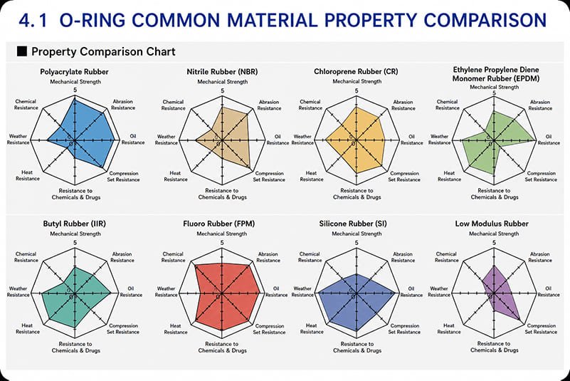
- for oil resistance choose nitrile rubber (NBR);
- for weather and ozone resistance choose chloroprene (CR);
- for heat resistance choose polyacrylate (ACM) or fluorocarbon (FKM);
- for high-pressure, high-wear service choose polyurethane (PU);
- and for low-temperature service that also demands oil resistance, choose epichlorohydrin copolymer (ECO).
| Material | Suitable Media | Service Temp. °C (Dynamic) | Service Temp. °C (Static) | Remarks |
|---|---|---|---|---|
| Nitrile rubber (NBR) | Mineral oil, gasoline, benzene | 80 | -30 to 120 | |
| Chloroprene rubber (CR) | Air, water, oxygen | 80 | -40 to 120 | Use with care in dynamic service |
| Butyl rubber (IIR) | Animal/vegetable oils, weak acids, alkalis | 80 | -30 to 110 | High compression set; not for mineral oils |
| Styrene-butadiene rubber (SBR) | Alkalis, animal/vegetable oils, air, water | 80 | -30 to 100 | Not for mineral oils |
| Natural rubber (NR) | Water, weak acids, weak alkalis | 60 | -30 to 90 | Not for mineral oils |
| Silicone rubber (VMQ) | High/low-temp oils, mineral oil, animal/vegetable oils, oxygen, weak acids, weak alkalis | -60 to 260 | -60 to 260 | Not for steam; avoid dynamic service |
| Chlorosulfonated polyethylene (CSM) | Hot oil, oxygen, ozone | 100 | -10 to 150 | Avoid dynamic service |
| Polyurethane rubber (PU) | Water, oil | 60 | -30 to 80 | Wear-resistant; avoid high-speed use |
| Fluorocarbon rubber (FKM) | Hot oil, steam, air, mineral acids, halogenated solvents | 150 | -20 to 200 | |
| PTFE | Acids, alkalis, most solvents | -100 to 260 | Not for dynamic service |
1. Natural Rubber (NR)
Made from latex tapped from rubber trees, natural rubber is a polymer of isoprene. It offers excellent abrasion resistance, high elasticity, and good tensile and elongation properties. On the other hand, it ages easily in air, turns sticky when heated, and swells or dissolves in mineral oil or gasoline. It resists alkalis but not strong acids. NR is the raw material for tapes, hoses, and rubber footwear, and it works well in vibration-damping parts and in products exposed to hydroxyl-bearing fluids such as automotive brake fluid and ethanol.
2. Styrene-Butadiene Rubber (SBR)
A copolymer of butadiene and styrene. Compared with natural rubber, SBR is more consistent in quality with fewer impurities, but mechanically weaker; it is often blended with NR.
Strengths:
- A low-cost, non-oil-resistant compound.
- Good water resistance; retains good elasticity below 70 Shore A.
- Poorer compression set at higher hardness levels.
- Compatible with most neutral chemicals and dry or fatty organic ketones.
Limitations:
- Not recommended for strong acids, ozone, oils, esters, fats, or most hydrocarbons.
- Widely used in tires, footwear, fabric coatings, and conveyor belts.
3. Butyl Rubber (IIR)
Polymerized from isobutylene with a small amount of isoprene, which retains a few unsaturated sites for vulcanization. Because steric hindrance from the methyl groups restricts molecular motion, gas permeability is low and resistance to heat, sunlight, and ozone is high, with good electrical insulation. It resists polar solvents such as alcohols, ketones, and esters. Typical service temperature: -54 to 110°C.
Strengths:
- Impermeable to most common gases.
- Good resistance to sunlight and ozone.
- Can be exposed to animal or vegetable oils and oxidizing chemicals.
Limitations:
- Not recommended for use with petroleum solvents, coal tar, or aromatic hydrocarbons.
- Used for chemical-resistant and vacuum-equipment rubber parts.
4. Hydrogenated Nitrile Rubber (HNBR)
Produced by hydrogenating NBR to remove part of its double bonds. Hydrogenation greatly improves heat and weather resistance over standard nitrile, while oil resistance stays comparable. Typical service temperature: -25 to 150°C.
Strengths:
- Better abrasion resistance than NBR.
- Excellent resistance to corrosion, tension, tearing, and compression set.
- Good resistance to ozone, sunlight, and general atmospheric exposure.
- Generally suitable for laundry and dishwasher detergents.
Limitations:
- Not recommended for alcohols, esters, or aromatic solvents.
- Widely used in air-conditioning and refrigeration, especially seals in R134a refrigerant systems.
- Automotive engine seals.
5. Ethylene Propylene Rubber (EPDM)
Copolymerized from ethylene and propylene. With no double bonds in the main chain, EPDM offers outstanding heat, aging, ozone, and stability performance — but cannot be sulfur-cured. To solve this, a small amount of a third diene monomer is introduced into the EP backbone, making sulfur vulcanization possible; the result is EPDM. Typical service temperature: -50 to 150°C. It has excellent resistance to polar solvents such as alcohols, ketones, glycol, and phosphate-ester hydraulic fluids.
Strengths:
- Good weathering and ozone resistance.
- Excellent resistance to water and chemicals.
- Compatible with alcohols and ketones.
- Withstands high-temperature steam; low gas permeability.
Limitations:
- Not recommended for food applications or exposure to aromatic hydrocarbons.
- Seals for high-temperature steam environments.
- Seals and parts for sanitary (bathroom) equipment.
- Rubber parts in braking systems.
- Seals in radiators (automotive water tanks).
6. Nitrile Rubber (NBR)
A copolymer of acrylonitrile and butadiene, with acrylonitrile content ranging from 18% to 50%. The higher the acrylonitrile content, the better the resistance to petroleum oils and hydrocarbon fuels — but the worse the low-temperature flexibility. Typical service temperature: -25 to 100°C. NBR is currently one of the most commonly used rubbers for oil seals and O-rings.
Strengths:
- Good resistance to oil, water, solvents, and high-pressure oil.
- Good compression set, abrasion resistance, and tensile strength.
Limitations:
- Not suitable for polar solvents such as ketones, ozone, nitro hydrocarbons, MEK, and chloroform.
- Used for fuel tanks, lubricant tanks, and rubber parts — especially seals — working in petroleum-based hydraulic oil, gasoline, water, silicone grease, silicone oil, diester lubricants, and glycol-based hydraulic fluids. Arguably the most versatile and lowest-cost rubber seal material available today.
7. Chloroprene Rubber (CR / Neoprene)
Polymerized from chloroprene monomer. Vulcanized CR offers good elasticity and abrasion resistance, tolerates direct sunlight, and has outstanding weathering resistance. It withstands severe flexing, resists refrigerants such as dichlorodifluoromethane and ammonia, and tolerates dilute acids and silicone-ester lubricants — but not phosphate-ester hydraulic fluids. It tends to crystallize and harden at low temperatures, has poor storage stability, and swells significantly in low-aniline-point mineral oils. Typical service temperature: -50 to 150°C.
Strengths:
- Good elasticity and compression set.
- Sulfur-free formulation, making it easy to process.
- Resists animal and vegetable oils.
- Physical properties are unaffected by neutral chemicals, fats, greases, many oils, and solvents.
- Flame-retardant.
Limitations:
- Not recommended for strong acids, nitro hydrocarbons, esters, chloroform, or ketones.
- Seals resistant to R12 refrigerant.
- Rubber parts and seals in household appliances.
- Ideal for parts in direct contact with atmosphere, sunlight, and ozone.
- Suitable for flame-resistant and chemical-resistant rubber products.
8. Chlorosulfonated Polyethylene (CSM / Hypalon)
A synthetic rubber originally patented by DuPont. It offers good heat, weather, and ozone resistance, as well as good acid resistance — often used where oxidizing chemicals (nitric acid, sulfuric acid) are present. Typical service temperature: -45 to 120°C.
Strengths:
- Good resistance to ozone, oxidation, and flame.
- Properties similar to CR, with better acid resistance.
- Excellent abrasion resistance.
- The same low-friction surface as NBR.
- Oil and solvent resistance between NBR and CR.
- Recommended for water-tightness applications.
Limitations:
- Not recommended for exposure to concentrated oxidizing acids, nitro hydrocarbons, esters, ketones, or aromatic hydrocarbons.
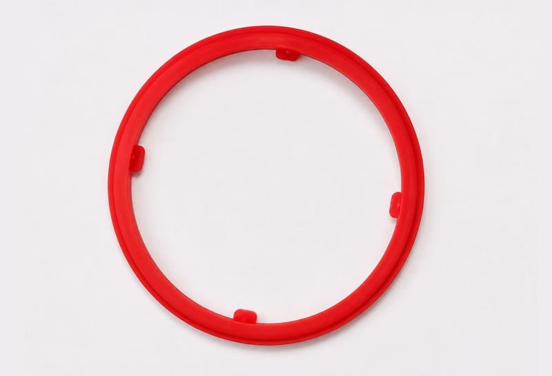
9. Silicone Rubber (VMQ)
Silicone rubber’s backbone is a chain of silicon and oxygen atoms (-Si-O-Si-). It offers outstanding resistance to heat, cold, ozone, and weathering, along with excellent electrical insulation. Its tensile strength is lower than most rubbers, and it is not oil-resistant.
Strengths:
- Formulated compounds can reach 1500 psi tensile strength and 88 lbs tear resistance.
- Good elasticity and compression set.
- Good resistance to neutral solvents.
- Outstanding heat resistance.
- Outstanding cold resistance.
- Excellent resistance to ozone and oxidative attack.
- Excellent electrical insulation.
- Good thermal insulation and heat dissipation.
Limitations:
- Not recommended for most concentrated solvents, oils, concentrated acids, or diluted sodium hydroxide.
- Seals and rubber parts in household appliances, such as electric kettles, irons, and microwave ovens.
- Seals and rubber parts in electronics, such as phone keypads, DVD damping pads, and cable-joint seals.
- Seals in products that contact the human body, such as water kettles and dispensers.
10. Fluorosilicone Rubber (FVMQ)
Fluorosilicone is silicone rubber modified with fluorine, combining the strengths of both fluorocarbon and silicone rubbers. It resists oils, solvents, and fuels, and performs well across high and low temperatures. Typical service temperature: -50 to 200°C.
Strengths:
- Suited to demanding applications requiring resistance to oxygenated chemicals, aromatic solvents, and chlorinated solvents.
Limitations:
- Not recommended for exposure to brake fluid, ketones, or hydrazine solutions.
- Used in aerospace components.
11. Fluorocarbon Rubber (FKM)
A family of rubbers containing fluorine in the molecule, with various types based on fluorine content (monomer structure). Its heat resistance exceeds that of silicone rubber, and it offers excellent chemical resistance, resistance to most oils and solvents (except ketones and esters), plus good weathering and ozone resistance. Low-temperature performance is relatively poor. Typical service temperature: -20 to 250°C; special formulations can tolerate down to -40°C.
Strengths:
- Withstands heat up to 250°C.
- Resists most oils and solvents — especially acids, aliphatic hydrocarbons, aromatic hydrocarbons, and animal/vegetable oils.
Limitations:
- Not recommended for ketones, low-molecular-weight esters, or nitro-containing mixtures.
- Automotive, motorcycle, and diesel-engine fuel systems.
- Seals for chemical plants.
12. Perfluoroelastomer (FFPM)
Strengths:
- Best-in-class heat resistance.
- Outstanding chemical resistance.
- Low outgassing.
- Excellent plasma resistance.
Limitations:
- Relatively poor low-temperature performance.
- High raw-material cost.
- Difficult to process.
- Perfluoroelastomers are widely used in the semiconductor and information industries — in thin-film processes such as PVD, CVD, and etching, and in various high-vacuum sealing applications.
13. Polyacrylate Rubber (ACM)
An elastomer polymerized mainly from alkyl ester acrylates. It offers good resistance to petroleum oils, heat, and weathering, but is weaker in mechanical strength, compression set, and water resistance — slightly below general oil-resistant rubbers. Typical service temperature: -25 to 170°C.
Strengths:
- Suitable for automotive transmission fluids.
- Good oxidation and weather resistance.
- Good flex-fatigue resistance.
- Excellent oil resistance.
- Suitable for automotive transmission and power-steering systems.
Limitations:
- Not suitable for hot water.
- Not suitable for brake fluid.
- No low-temperature capability.
- Not suitable for phosphate esters.
- Seals for automotive transmission and powertrain systems.
14. Polyurethane Rubber (PU)
Polyurethane rubber has outstanding mechanical properties — its hardness, elasticity, and abrasion resistance are difficult for other rubbers to match. Aging, ozone, and oil resistance are also quite good. Typical service temperature: -45 to 90°C.
Strengths:
- Wear-resistant and pressure-resistant.
Limitations:
- Poor heat resistance.
- Industrial high-pressure, wear-resistant seals, such as hydraulic cylinder seals.
- High-pressure, high-load electrical systems.
Key Factors in O-Ring Material Selection
Selecting an O-ring material mainly involves the following considerations:
- The O-ring’s duty: whether the ring serves in static, dynamic, or sliding sealing.
- Machine duty: whether the machine runs continuously or intermittently, how long each cycle lasts, and whether shock loads act on the seal.
- Working medium: whether the medium is a gas or liquid, along with its physical and chemical properties.
- Working pressure: pressure magnitude, fluctuation amplitude and frequency, and the maximum instantaneous pressure.
- Working temperature: including transient spikes and temperatures during thermal cycling.
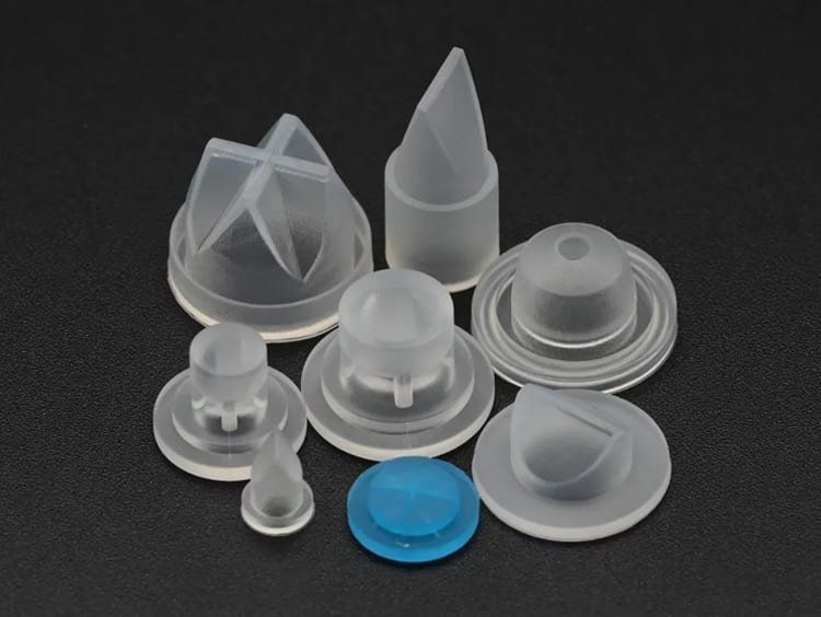 LSR Injection Molding
 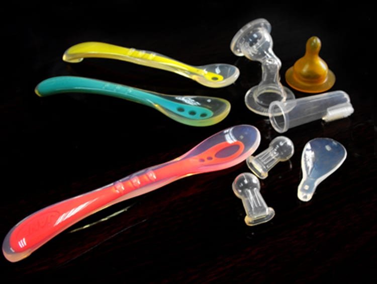 Silicone Overmolding
 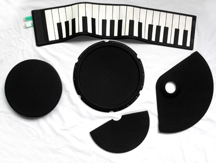 Compression Molding
 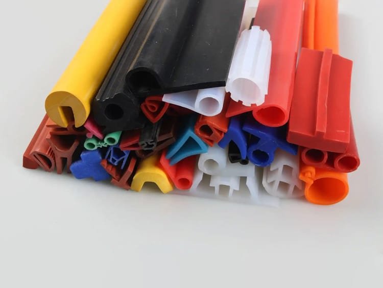 Silicone Extrusion
 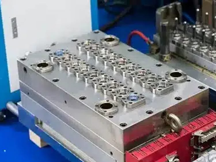 In-house Tooling