
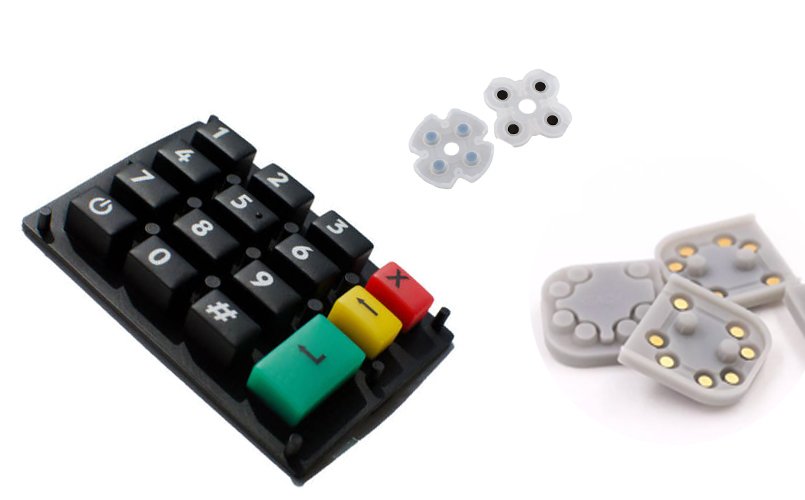
Silicone rubber keys are a direct point of interaction in consumer electronics, home appliances, and medical devices. Although they appear simple, their performance depends on many design details. From a light-touch button on a baby bottle warmer to the precise return of a smartphone side key and the durability required for automotive controls, small structural changes can produce noticeable differences in feel and reliability.
1. Structure of a Silicone Rubber Keypad
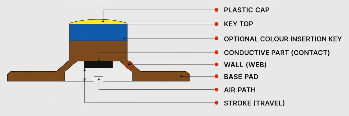
A silicone rubber key combines an elastomer with functional features. It typically consists of the silicone rubber body, keycap, base, and support or locating features. Each element has a specific role, and together they determine service life and reliability.
1.1 Silicone Rubber Body
The silicone rubber body is the primary functional material. It is usually made from high-temperature-vulcanized silicone rubber (HTV) by compression molding. In addition to providing return force, it may also seal against dust, absorb impact, and transfer the applied load.
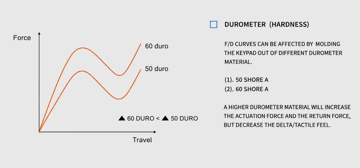
Hardness selection: Shore A 20 to 80 is commonly used. Softer silicone, such as Shore A 30, provides a lighter touch but may collapse too easily. Harder silicone, such as Shore A 60, provides better support but requires more force. The hardness should match the product and use case, such as a children’s toy or an industrial instrument.
The body often includes bosses or ribs that control downward travel and help the conductive contact, or a metal dome, engage the PCB correctly.
1.2 Keycap
The keycap is the surface touched by the user. Its design should provide adequate grip, clear markings, and the correct fit. Common materials include ABS, PC, and two-shot combinations such as clear PC with colored silicone. Mold texture, laser marking, and UV transfer printing also affect feel. For example, a fine matte texture can improve grip when the user’s fingers are wet.
1.3 Base and Support Features
The base secures the keypad to the product housing and limits lateral movement of the silicone body. This helps prevent off-axis loading that can shorten service life. Some designs add support posts or stop ribs. Automotive keys, for example, may use metal inserts to increase stiffness under repeated vibration.
Common Structural Arrangements
Direct-acting design: The center of the keycap is pressed vertically, causing the silicone body to deform as a whole. The structure is simple and cost-effective, and is commonly used in remote controls and calculators.
Side-actuated design: A force applied to the side of the keycap is transferred through an inclined web and converted into vertical movement. This saves height and is often used for smartphone side keys and earbud charging-case buttons.
2. Force-Travel Curve
The most immediate measure of a silicone key is its tactile feel. That feel is defined largely by the force-travel curve, which records how force changes as the key moves through its stroke.
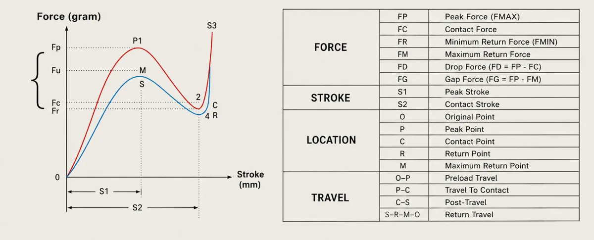
Four Key Stages of the Curve
For a typical snap-action silicone key, the curve can be divided into four stages:
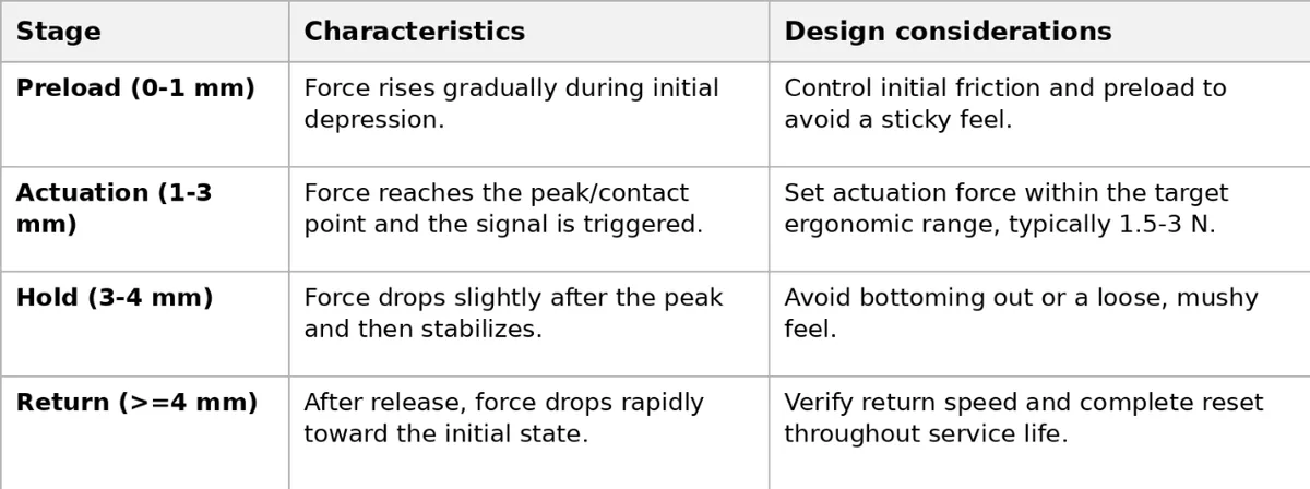
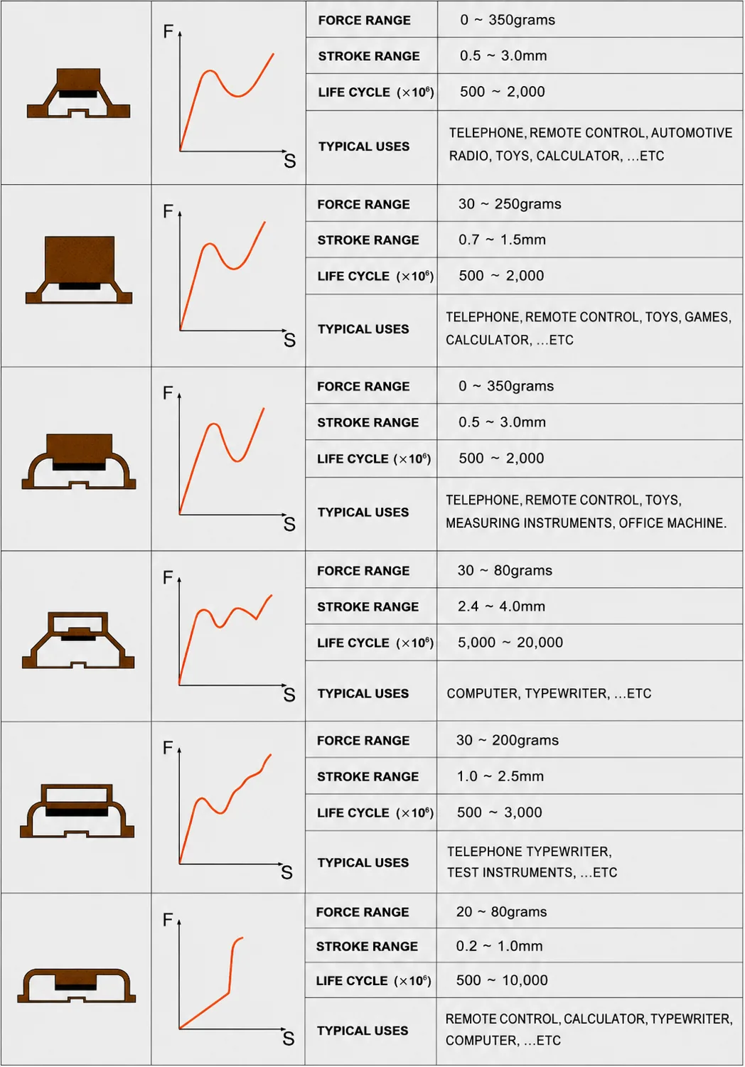
A well-designed curve should feel light at the start, provide a clear actuation point, and return promptly after release.
Key structural parameters include silicone hardness, web angle, and boss height. Higher hardness generally increases the force level. A larger web angle can reduce initial force but may also reduce available travel. Boss height affects the actuation travel.
3. Web Design
The inclined web is the primary load-transfer feature in a silicone key. It converts the applied force into vertical movement and directly affects travel, force, and service life.
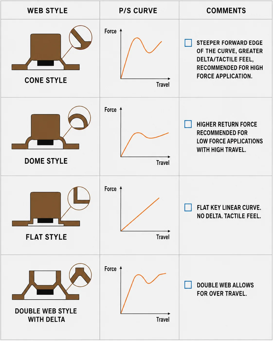
Relationship Between Web Geometry and Performance
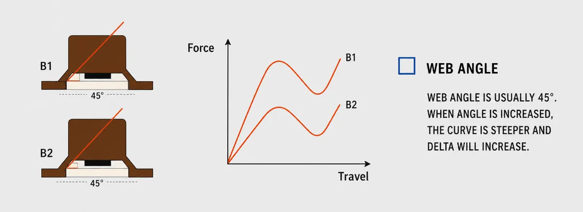
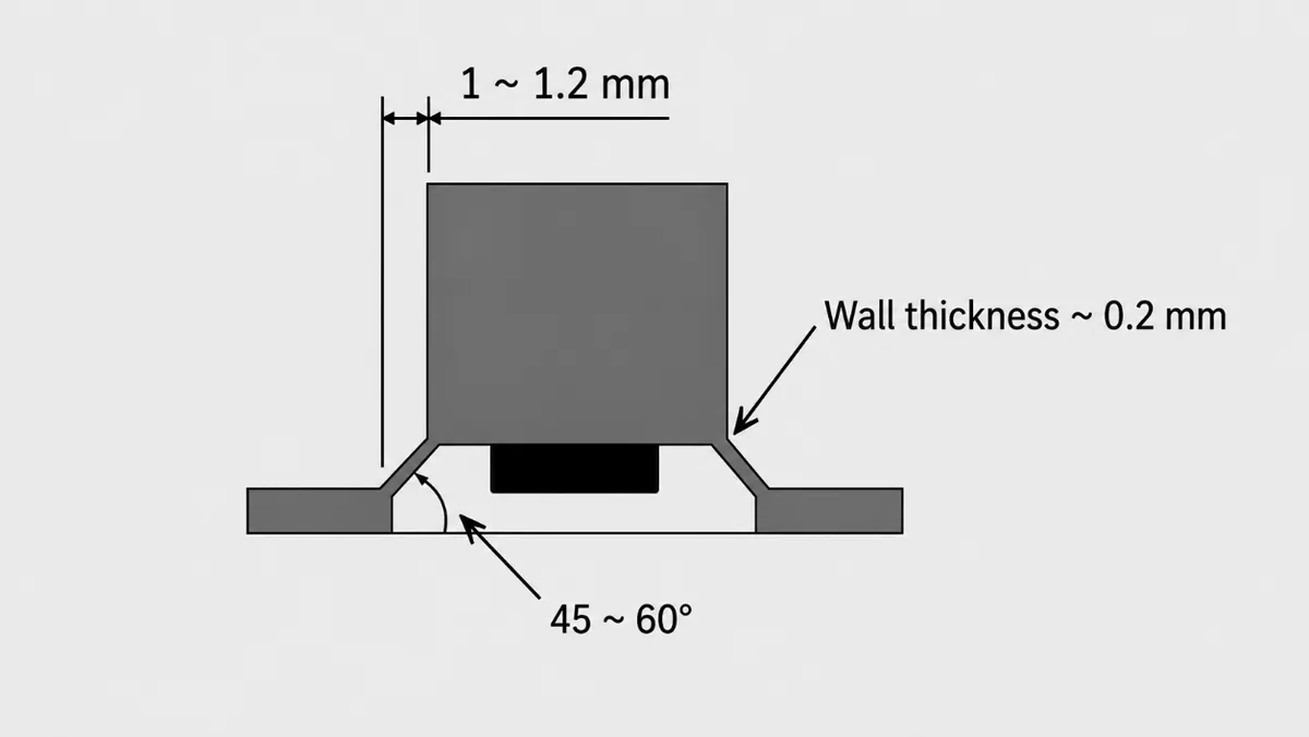
Angle alpha, measured between the web and the horizontal plane:
If the angle is too small, for example 15 degrees or less, the initial force increases (F = mu x N / cos alpha, where mu is the coefficient of friction), and the key feels stiff.
If the angle is too large, for example 35 degrees or more, travel is reduced (travel is approximately web length x sin alpha), and stress concentration may cause cracking.
As a practical reference, consumer-electronics keys often use an angle of 20 to 28 degrees to balance tactile feel and strength.
Web length L:
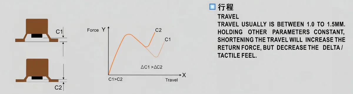
Web length determines total travel (travel is approximately L x sin alpha). It must be coordinated with the position of the conductive contact on the PCB so that the key does not bottom out before contact is made.
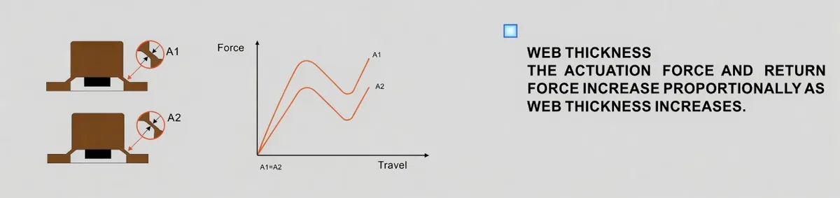
Web thickness t:
A web thinner than about 0.8 mm may fail from fatigue under frequent operation. A web thicker than about 1.5 mm increases the initial force. A typical thickness is 1.0 to 1.2 mm, with an R0.3 to R0.5 mm fillet at the root to reduce stress concentration.
Web Optimization for a TWS Earbud Side Key
In one project, the initial design used a 25-degree web angle and a 5 mm web length. Testing showed that the actuation force was high at 3.5 N, and users found the key tiring to press. Increasing the angle to 28 degrees and the length to 5.5 mm reduced the actuation force to 2.8 N and increased travel by 0.3 mm. The tactile feel improved, and the key passed 50,000 cycles without cracking.
4. Conductive Pills
A silicone rubber keypad switches a signal on and off. The component that completes this function is the conductive pill, also called a conductive contact, on the underside of the key.
4.1 How Conductive Pills Work
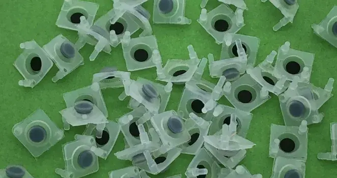
Conductive pills are usually circular or near-circular pads made from carbon-filled silicone rubber or a metal-coated polymer, such as nickel-coated silicone.
When the key is pressed, the silicone mat deforms and moves the conductive pill toward the contact pattern on the PCB. Once sufficient force is applied, the pill bridges the PCB electrodes and completes the circuit. When the key is released, the silicone returns to its original shape, the pill separates from the electrodes, and the circuit opens.
Electrical contact is created through elastic deformation rather than a rigid point contact. The resilience and surface condition of the pill therefore affect contact-resistance stability. Insufficient recovery can cause intermittent contact after long-term use, while an excessively smooth surface may produce momentary opens from contact bounce.
4.2 Conductive Pill Design
The following parameters require close control:
Size and dimensional distribution: Conductive-pill thickness and diameter must be controlled within a narrow range. Where particulate conductive compounds are used, a particle-size range of 0.3 to 1.0 mm and a narrow distribution around D50 +/- 0.05 mm may be specified. Excessive variation can create uneven local pressure and intermittent electrical contact.
Compression set: This is an important indicator of fatigue resistance. A compression set below 15% is recommended under the stated test condition of 25% compression at 70 degrees C for 22 hours. Higher compression set can reduce contact force after extended use.
Material and surface control: Carbon-filled contacts typically require controlled carbon-black content, often 15% to 25%. Too little reduces conductivity, while too much increases hardness. Metal-coated contacts require adequate coating adhesion to prevent flaking and possible short circuits.
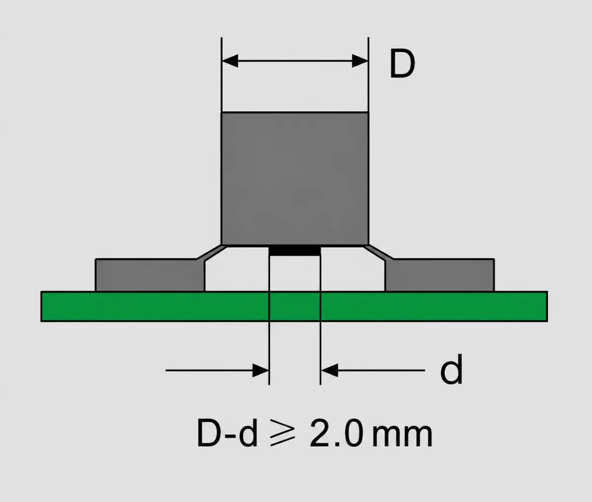
Common conductive-pill diameters include 2.0, 2.5, 3.0, 3.5, 4.0, 4.5, 5.0, 6.0, and 8.0 mm.
Common conductive-pill thicknesses include 0.4, 0.5, and 0.6 mm.
5. Conductive Ink
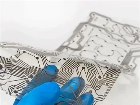
Conductive ink forms the PCB contact pattern and is the final interface between the silicone key and the circuit. The ink type and application process directly affect electrical consistency.
5.1 Conductive-Ink Application: Screen Printing, Spraying, or Pad Printing
Screen printing: Ink is transferred through a mesh screen onto the PCB. It can achieve line widths and spacing down to about 0.1 mm and is suitable for low-volume, high-precision applications such as smartphone side keys. Screen tension must be controlled. Insufficient tension can produce uneven ink thickness; a typical target thickness is 15 to 30 micrometers.
Spray coating: A spray gun applies the ink over a larger area and can provide high throughput. It is suitable for large keypad panels, such as appliance controls. Air pressure, typically 0.2 to 0.4 MPa, and nozzle distance, typically 10 to 15 cm, must be adjusted to prevent runs or incomplete coverage.
Pad printing: This process transfers ink with a silicone pad, similar to stamping. It is useful on curved or irregular surfaces, but requires careful control of ink rheology and generally costs more than screen printing.
5.2 Common Conductive-Ink Formulations
Carbon ink: Carbon black is used as the conductive filler. It costs less than silver ink and has good environmental stability, but its volume resistivity is higher, typically 10 to 30 mOhm-cm. It is suitable for consumer-electronics keys with low current requirements.
Silver ink: Silver powder provides low resistivity, typically 0.1 to 1 mOhm-cm, and high conductivity. It is more expensive and may require passivation to limit oxidation. It is often used in automotive electronics, medical devices, and other applications that require higher electrical reliability.
Hybrid ink: A blend of carbon and silver balances cost and electrical performance. It is increasingly used in mid- to high-range appliance controls.
6. Silicone Keypad Mat Design
The silicone mat is more than a cover. Its detailed geometry directly affects tactile feel, service life, sealing, and reliability. The following four features require careful attention.
6.1 Sealing Rib
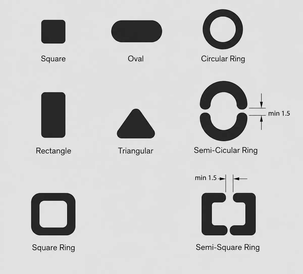
To improve water resistance, such as to IP65, an annular sealing rib is often added around the edge of the mat. The rib may stand 0.1 to 0.2 mm above the surrounding keypad body, with a width of 0.3 to 0.5 mm and a housing clearance of no more than 0.05 mm. A rib that is too thick can lift the keypad and make it feel stiff, while a rib that is too thin may not seal effectively.
6.2 C-Shaped Air Pocket
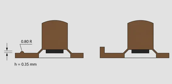
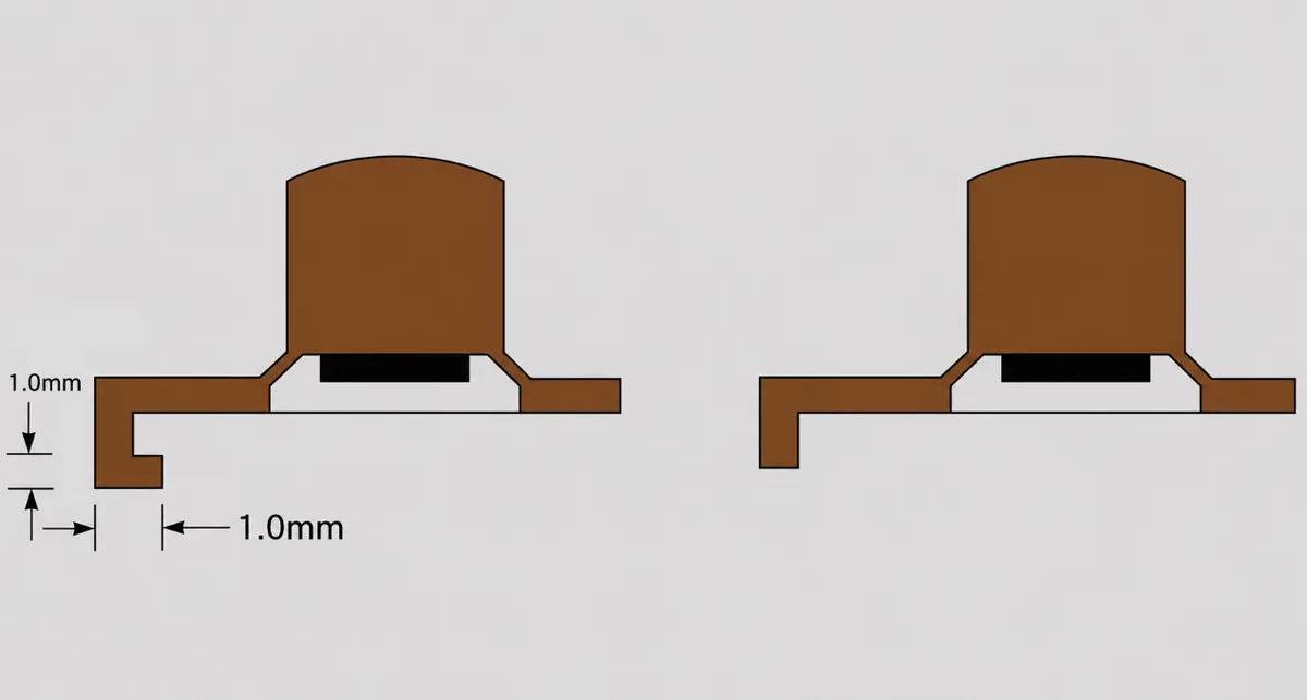
A C-shaped recess under the key, typically 0.2 to 0.3 mm deep and 0.5 to 0.8 mm wide, provides space for displaced air and helps prevent a sticky or sluggish feel. In the cited test, this feature reduced return time by 15% and increased service life by 20% by reducing silicone fatigue.
6.3 Air Vent Channels
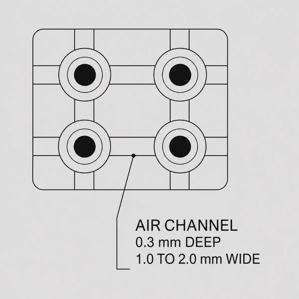
Air trapped under the silicone can create noise when the key is pressed. Radial vent channels in the keypad mat, typically 1 to 2 mm wide and 0.3 mm deep, allow compressed air to escape and produce a cleaner, more consistent feel.
6.4 Openings in the Mat: Balancing Function and Strength
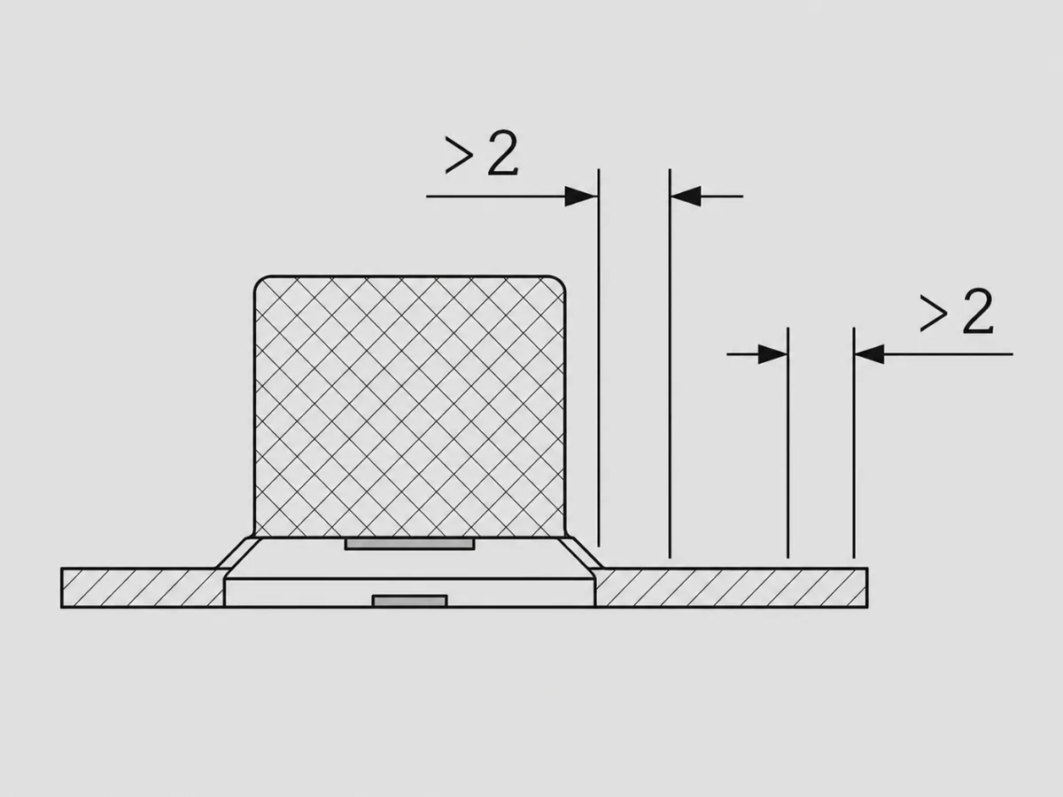
If the keypad integrates an LED indicator or sensor, the mat may require a light opening or sensor opening. A light opening should include an R0.1 to R0.2 mm rounded or flared edge to reduce uneven brightness caused by refraction. Sensor openings should hold a diameter tolerance of about +/-0.05 mm to reduce the risk of false triggering.
7. Silicone Light Guides
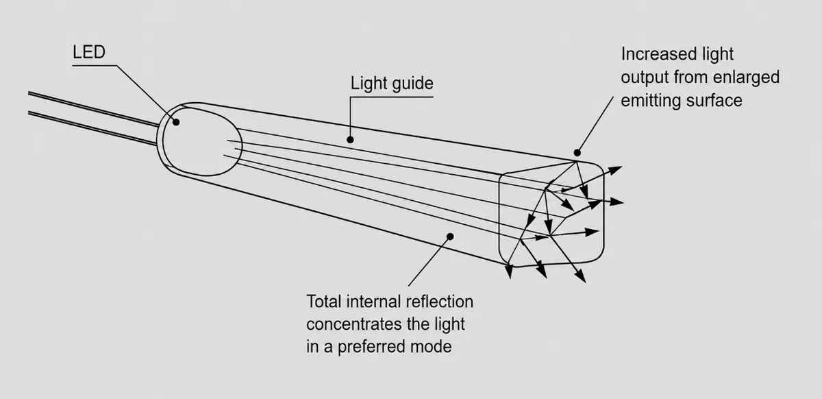
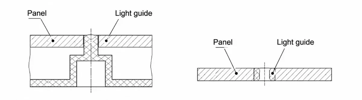
Consider a smartwatch key used in low light, or a backlit microwave keypad where scattered light makes the symbol difficult to read. A silicone light guide uses optical-grade silicone and controlled geometry to distribute light from an LED more evenly. The goal is to reduce light loss, weak illumination, and visible hot spots.
7.1 Advantages of Silicone Light Guides
Compared with rigid plastics such as PC and PMMA, silicone offers high elasticity and good resistance to aging.
High light transmission: Food-contact-grade silicone can provide light transmission above 85%, while specialized optical formulations may exceed 90%. It is compatible with the broad visible spectrum of LEDs, approximately 400 to 700 nm, and can limit color shift.
Impact protection:
During repeated key operation, a silicone light guide can deform slightly with the keypad body. This reduces hard contact that could damage the LED package.
Water and dust resistance: Silicone can conform to small gaps between the light guide and housing. For designs below IP65, this physical sealing effect may provide much of the required protection.
7.2 Design Guidelines and a Practical Sizing Formula
A common mistake is to reduce thickness without considering optical performance. A light guide that is too thin may lose too much light. A very thick guide increases material use and may be harder to mold. The following empirical relationship can be used as an initial estimate:
Minimum effective thickness = tan(LED emission angle alpha) x light-diffusion distance L x 1.2 safety factor
Example: If alpha = 60 degrees and L = 3 mm, the estimated thickness is tan 60 degrees x 3 x 1.2, or approximately 6.2 mm. A nominal value of 6 mm may be selected for initial evaluation.
Surface finish also matters. Mold texturing can create a diffused surface. Where more directional light is required, a shallow microlens can be added to the top of the guide, typically as a curved surface 0.1 to 0.2 mm deep.
In one project, insufficient curvature caused a discontinuous light band at low temperature as the silicone stiffened. Increasing the corner radius from 0.3 to 0.5 mm resolved the issue.
8. Silicone Locating Posts
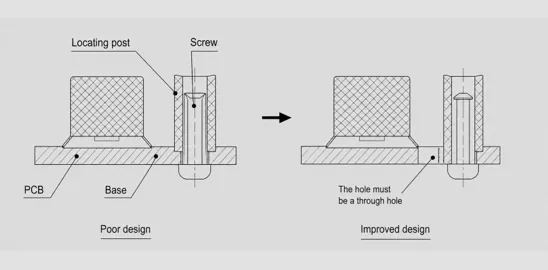
A light guide controls the path of light; a locating post controls the position of the assembly. Silicone keys often interface with a PCB, housing, and adjacent keys. Poor location control can cause noise, misalignment, or functional failure. The following designs are commonly used.
8.1 Stretch-Fit Locating Post

This design is suitable for soft housings such as TPU, or for thin-wall keys under 2 mm. One example is a silicone button used in a wireless-earbud charging case.
Design considerations:
The post height should be at least 1.5 times the compression or pull-through distance after assembly to reduce the risk of disengagement.
A post diameter of approximately one-third to one-half of the height is a useful starting point. A smaller post may tear, while a larger post may be difficult to compress or pull through.
Shore A 40 to 50 is commonly suitable. Harder material may crack during stretching, while softer material may not locate the part securely.
In one TWS earbud project, a Shore A 60 post had a breakage rate above 5% during production assembly. Changing to a lower hardness resolved the issue.
8.2 Push-In Locating Post
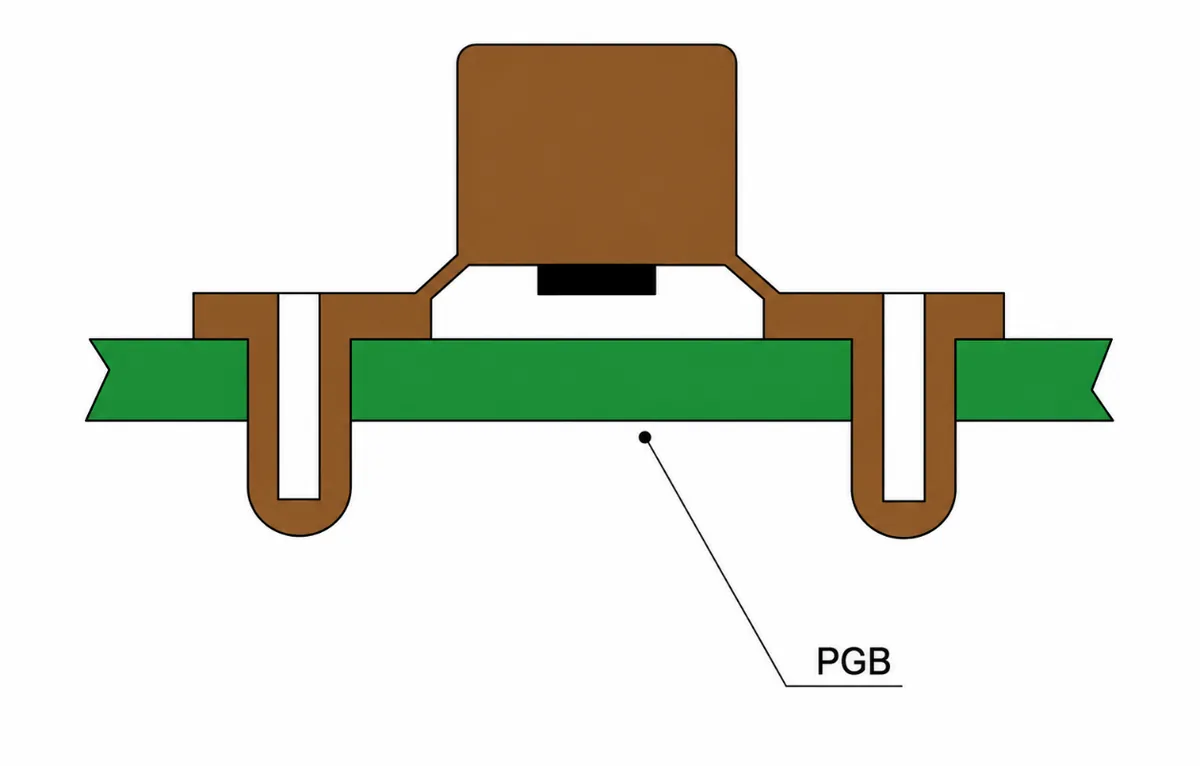
This design is suitable for keypad arrays, such as calculators and remote controls, where lateral movement between adjacent keys must be limited.
Design considerations:
Use a guide groove at least 0.2 mm deep, with an entry angle of about 15 to 30 degrees. A steep angle is difficult to assemble, while a shallow angle may not retain the keypad securely.
Provide a one-sided clearance of approximately 0.05 to 0.1 mm between the locating surface and the mating hole to allow controlled compression.
For poka-yoke assembly, an asymmetric notch can be added, such as a wide feature on one side and a narrow feature on the other.
8.3 Barbed Locating Post
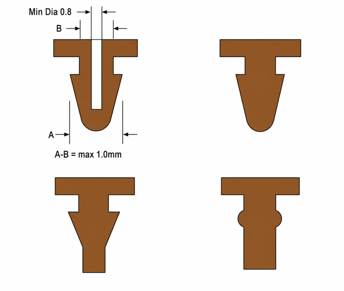
This design is suitable for modules that may need periodic removal for service, such as an appliance keypad panel separated from its control box.
Design considerations:
Keep the barb angle at 30 degrees or less. A larger angle can make molding and assembly difficult, while a very small section may tear.
A barb length of 0.3 to 0.5 mm is typical. A longer barb may damage the mating surface, while a shorter barb may release too easily.
The required removal force should be calculated.
Removal force = silicone shear strength x barb cross-sectional area x 1.5 safety factor
Example: With a shear strength of 3 MPa and a barb area of 1 mm2, the estimated removal force is about 4.5 N. This helps prevent unintended removal by the user.
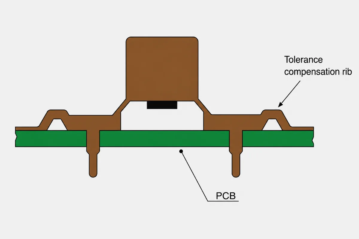
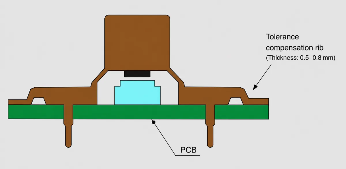
8.4 Locating Large Keypad Mats
For a large part, dimensional variation may exceed the allowable key-position tolerance. Flexible features can be added to the mat, or selected areas can be made thinner, so the mat has enough compliance to absorb assembly variation.
9. Minimum Overall Key Size
A common design mistake is to make a silicone key as small as the tooling will allow. If the key is too small, however, both tactile feel and fatigue life can be reduced.
9.1 Ergonomic Requirements
ISO 9241-410 recommends an adult finger-contact area equivalent to approximately a 6 mm diameter for a circular key or a 5 mm side length for a square key. Below this range, the finger may not contact the key reliably or apply force comfortably. The issue is more noticeable for older users and gloved operation.
9.2 Material-Fatigue Limits
Silicone fatigue life is closely related to strain. The cited test data indicate that when key diameter falls below 5 mm, the local strain may become excessive and cycle life can fall from about 100,000 cycles to below 20,000 cycles for the referenced 10-degree key design. For consumer products such as remote controls and calculators, a minimum diameter of 6 to 8 mm is a useful starting point. High-reliability medical-device keys may require 8 to 10 mm.
Design note: For a non-circular key, calculate the projected contact area and keep it at least equal to the area of a 6 mm diameter circle.
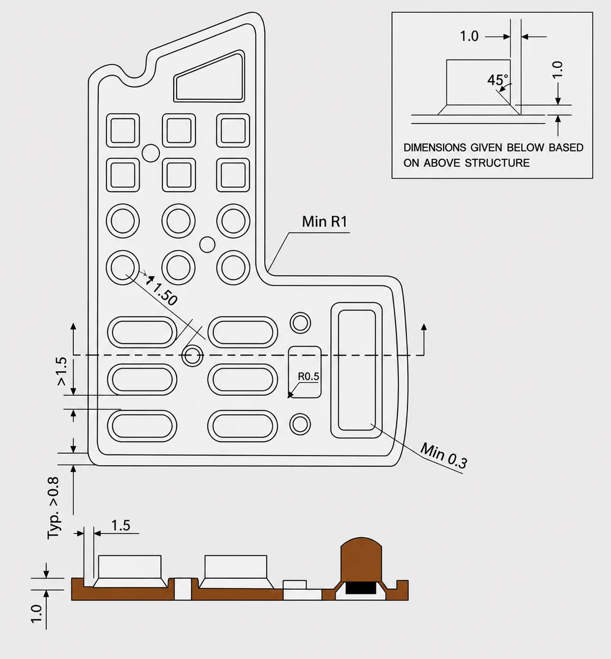
10. Clearance Between the Key and Housing
A key that binds during depression or makes noise during return often has insufficient or poorly controlled clearance to the housing.
10.1 Why Clearance Is Required
A silicone key expands laterally when pressed. If the clearance to the housing is too small, the expanding silicone rubs against the housing and can cause:
Higher pressing resistance and a rough or dragging feel.
Wear or flash-like damage along the key edge after repeated rubbing.
In severe cases, the key may bind in the housing and fail to return.
10.2 Recommended Clearance
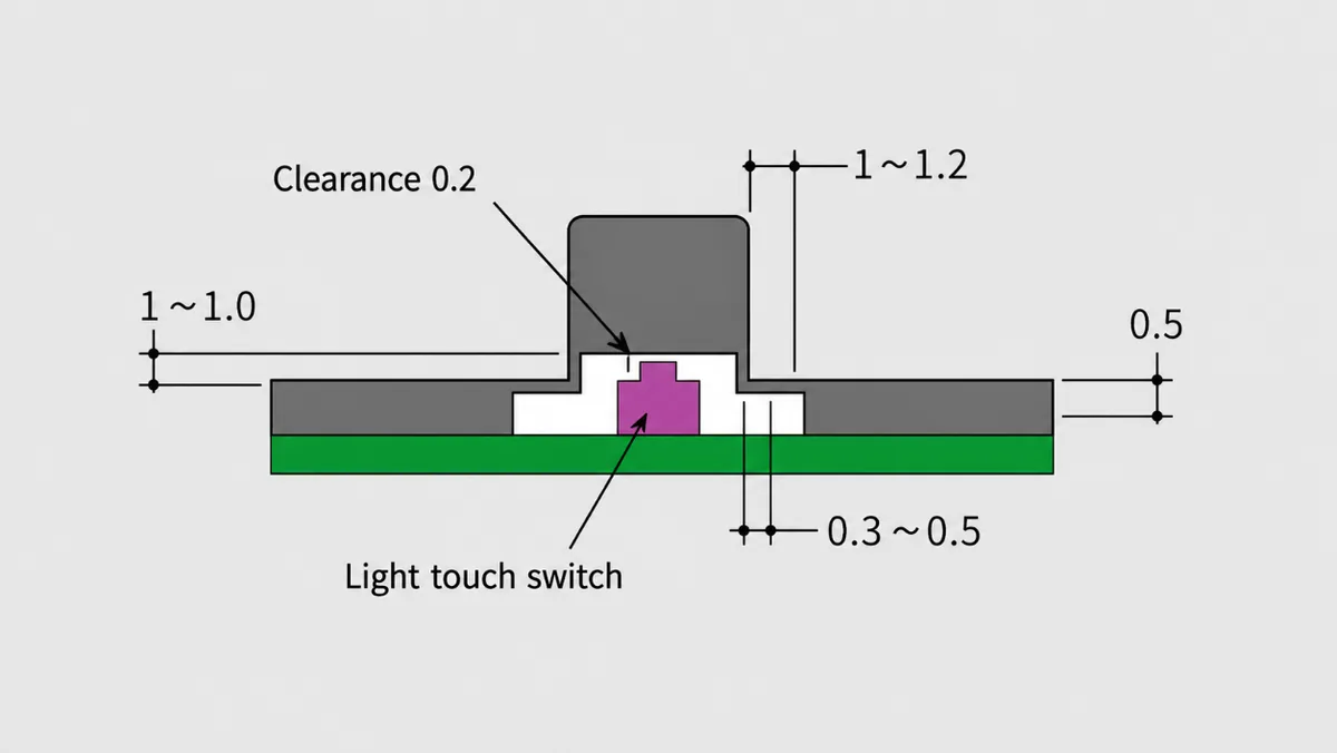
A one-sided clearance of 0.3 to 0.5 mm is commonly used, then adjusted for the following factors:
Key travel: Greater travel, especially above about 1.5 mm, produces more lateral expansion and may require more clearance.
Silicone hardness: Soft silicone at Shore A 30 to 40 deforms more than Shore A 50 to 60 material and may require an additional 0.1 to 0.2 mm of clearance.
Assembly tolerance: For a keypad assembled to or overmolded with a housing, provide an additional tolerance allowance of about 0.1 mm where needed.
Avoid a zero-clearance design. In one project, a nominal clearance of 0.1 mm was specified despite limited tooling capability. During production, about 80% of the keys produced return noise, and the tool had to be modified to increase the clearance.
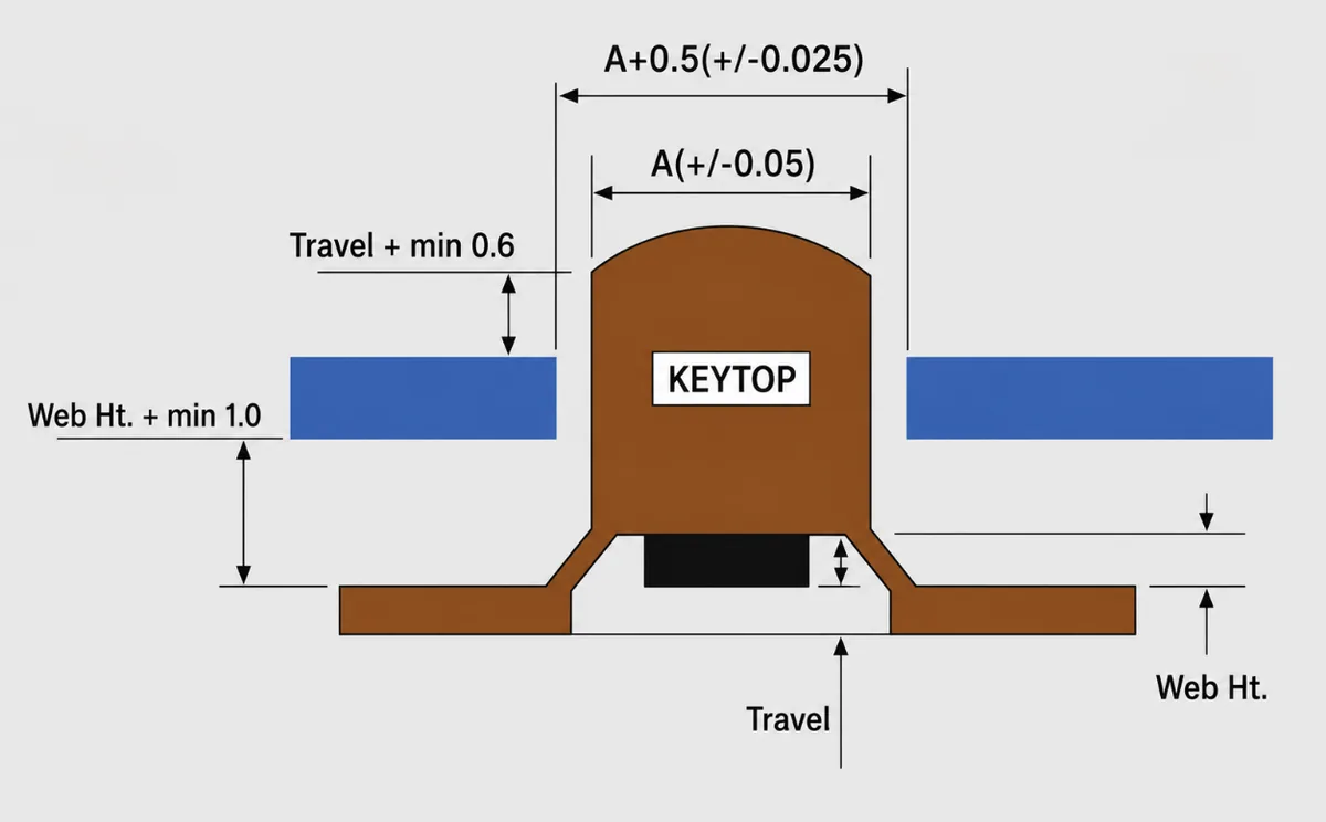
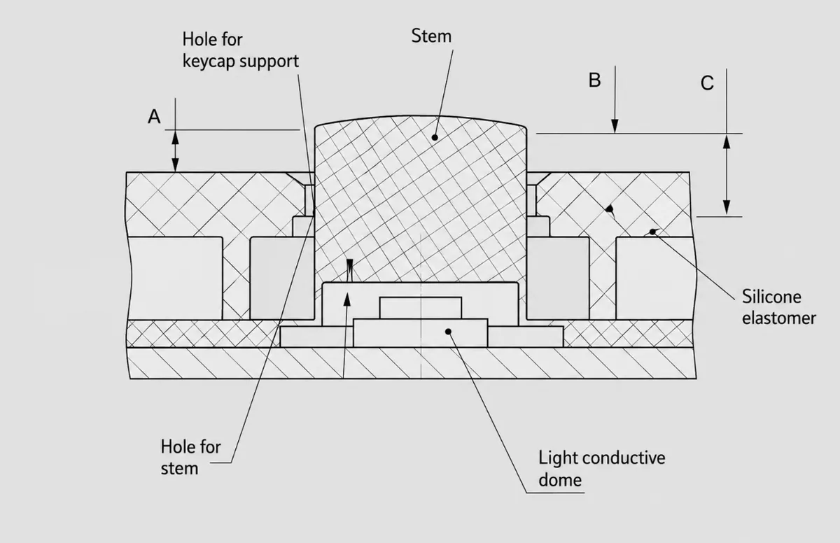
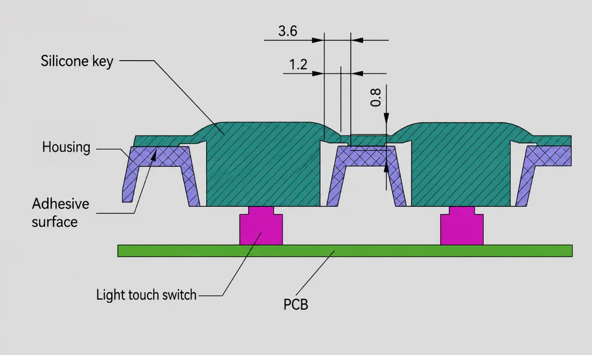
D: Free travel before the tactile switch is engaged. A typical value is 0.2 mm. For keys that require greater protection against accidental actuation, D may be increased to 0.5 to 1.0 mm.
A: Height from the highest point of the key to the housing surface.
Design relationship: A = tactile-switch travel + D + 0.8 to 1.2 mm.
B: Height from the straight side of the keytop to the outer corner of the key-opening wall.
Design relationship: B = D + 0.2 to 0.4 mm.
C: Height from the straight side of the keytop to the inner corner of the key-opening wall.
Design relationship: C >= tactile-switch travel + D + 1.5 mm.
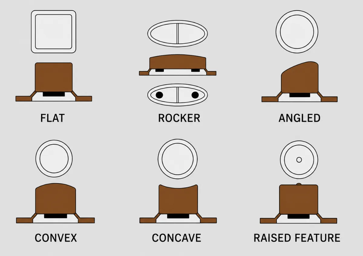
11. Keytop Profiles: Flat, Concave, or Convex-
Keytop geometry affects both appearance and how the finger locates and presses the key. The following profiles are commonly used.
11.1 Flat Keytop
A flat keytop, flush with or slightly below the housing, is common on industrial equipment and instruments. It is easy to clean and provides a simple appearance. Consider the following details:
Add a small 0.3 to 0.5 mm raised locator in the center where needed to improve finger location and reduce slipping.
Use an R0.2 to R0.3 mm edge radius to reduce stress concentration and the risk of cracking.
11.2 Concave Keytop
A concave keytop, typically recessed by 0.2 to 0.5 mm, provides good finger location and is common in consumer electronics and remote controls. A radius of about R1 to R2 mm can conform to the fingertip and improve control. Consider the following details:
Keep the recess depth below about one-third of the key travel. For example, with 1 mm of travel, use a recess no deeper than about 0.3 mm. A deeper recess may create raised edges that interfere with adjacent keys.
For closely spaced keys, such as a telephone keypad, use a consistent curvature to reduce accidental presses.
11.3 Convex Keytop
A convex keytop, typically raised by 0.3 to 0.8 mm, is common on game controllers and children’s products. The raised surface is easy to locate by touch and provides a direct tactile reference. Consider the following details:
Coordinate the convex height with the available travel. A practical starting point is no more than the key travel plus 0.2 mm. Excessive height may cause the key to bottom out before full actuation.
Add a non-slip texture, such as a fine matte finish, where perspiration or wet fingers are expected.
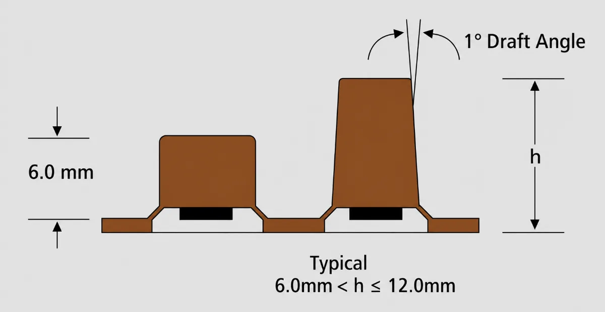
12. Draft Angle
Silicone is highly elastic, but insufficient draft can still deform the key during demolding or increase wear on the tool.
12.1 Why Draft Is Required
During demolding, the silicone rubs against the cavity and core surfaces. Without adequate draft, deep key features may stretch or distort, causing height variation, dimensional nonconformance, or drag marks.
12.2 Selecting the Draft Angle
Standard keys with a depth of 1.5 mm or less: Use approximately 0.5 to 1 degree per side. This supports demolding without creating a visibly tapered surface.
Deep keys over 2 mm: Increase the angle to about 1 to 1.5 degrees. A stepped draft can also be used, with less draft near the base and more near the top, to balance release and appearance.
Products with strict cosmetic requirements: Draft may be placed on a non-cosmetic surface, such as the back of the key, so the visible wall remains nearly vertical. This generally reduces demolding efficiency.
In one project, a draft angle of only 0.3 degrees caused the silicone to drag on the core. The resulting wear required tool repair after three months and increased cost by about 15%.
13. Stabilizing Posts
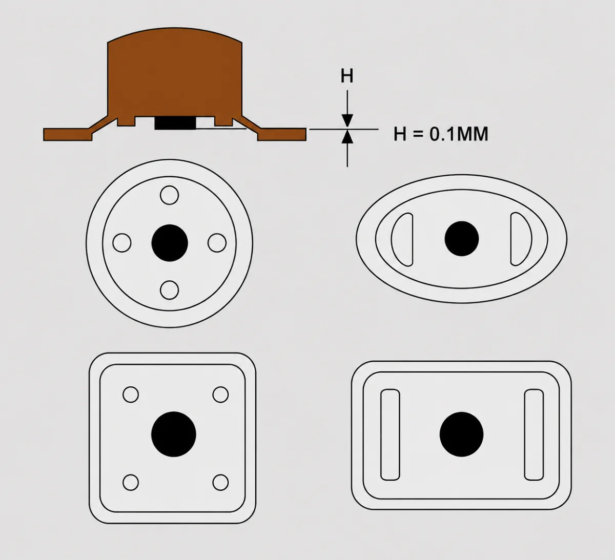
If a key rocks from side to side or shifts after assembly, a stabilizing post can help control its position.
13.1 Primary Functions
Limit rocking: A post engages a locating hole in the housing and constrains movement in the X and Y directions.
Assist assembly: The post helps align the key with the housing and reduces binding caused by positional error.
Distribute load: The post can reduce rubbing between the key edge and housing and lower long-term wear.
13.2 Design Considerations
Location: Place posts near the center or at opposing corners of a large rectangular key. Keep them clear of functional areas such as legends, tactile bosses, and conductive contacts.
Size: A diameter equal to roughly one-third to one-half of the key thickness is a useful starting point. For a 2 mm thick key, for example, a post diameter of 0.8 to 1.0 mm may be suitable. Keep the post height below the available key travel to prevent interference with the housing.
Fit clearance: Use a one-sided clearance of approximately 0.05 to 0.1 mm to the housing hole. A tight fit may tear the post, while a loose fit allows rocking. Use the same silicone compound as the keypad body, typically Shore A 30 to 40 for the cited design, to avoid movement caused by a hardness mismatch.
 LSR Injection Molding
  Silicone Overmolding
  Compression Molding
  Silicone Extrusion
  In-house Tooling