
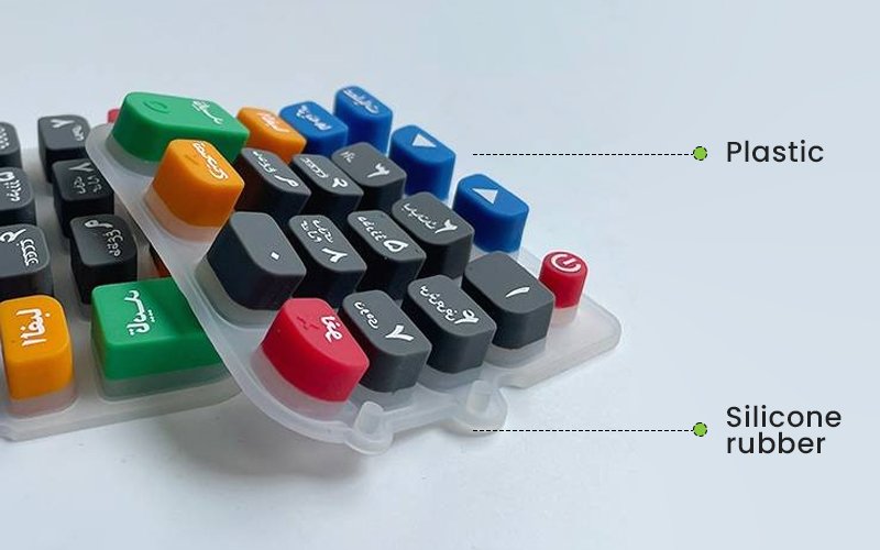
P+R keypad, short for Plastic + Rubber keypad, combines rigid plastic keycaps with an elastic silicone rubber keypad or keymat. The plastic section defines the visible key surface, shape, color and legend, while the silicone rubber section provides elastic movement, return force, sealing and the interface to the switch underneath. Compared with a conventional one-piece silicone rubber keypad, this construction gives designers a harder and more precisely defined key surface without losing the compliance and sealing capability of silicone rubber.
For engineers, however, a successful P+R keypad is not simply a plastic cap bonded onto silicone. Key height, dome position, travel, clearance, keycap flatness, rubber geometry, support structure and assembly tolerance all affect how the finished keypad feels and functions.
What is a P+R Keypad?
A typical P+R keypad contains two main molded components.
The upper component is an injection-molded plastic keycap. Depending on the appearance, strength, wear resistance and backlighting requirement, the cap may use materials such as ABS, PC, PC/ABS, PBT or PMMA.
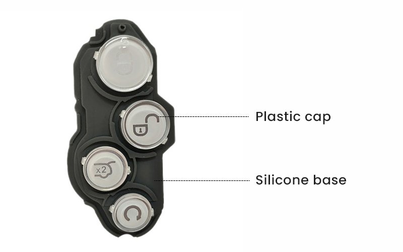
Underneath the cap is a molded silicone rubber keymat. It connects individual keys into one assembly and provides elastic movement when the operator presses and releases the button.
The complete switch stack may also contain a stainless-steel or plastic support plate, PET dome sheet, metal dome, PCB, conductive contact structure and LEDs.
A representative structure can therefore be simplified as:
Plastic keycap → silicone rubber base → support/stiffener → metal dome or switch → PCB.
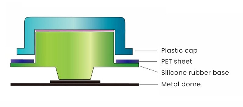 The plastic cap and silicone section are usually produced separately and then assembled through adhesive bonding or a mechanical retention structure. Some designs can use insert-molding or other integrated processes, but material compatibility and geometry need to be evaluated during DFM.
Why Combine Plastic and Silicone Rubber?
A full silicone keypad works well when designers need a soft surface, integrated sealing and relatively simple tooling. But silicone alone has limitations when the visible button needs a rigid surface or highly controlled appearance.
A P+R keypad solves this by separating the functions of the two materials.
The plastic cap provides dimensional rigidity, sharper edges and controlled surface texture. It also creates more options for metallic finishes, painted surfaces, laser-etched legends, transparent windows and other cosmetic treatments.
The silicone rubber underneath provides elasticity and allows the key to move vertically. It can also form sealing ribs, skirts and flexible retention features around the keypad.
This structure is especially useful when an HMI requires the tactile behavior of an elastomer keypad but the user should touch a hard plastic surface.
P+R Keypad Stack-Up
One of the most important parts of P+R keypad design is the vertical stack.
Every component between the visible key surface and the PCB consumes space. If these dimensions are treated independently, tolerance accumulation can create preload, excessive free play, inconsistent key height or poor tactile response.
A compact P+R assembly may include the plastic cap, adhesive layer, silicone contact boss, metal support plate, dome sheet, metal dome and PCB.
In the reference design, the PCB, dome structure, silicone contact, support plate and keycap are designed together rather than as separate parts. The same design also shows why clearance must be maintained around LEDs and other components that could interfere with downward key movement.
This principle remains important even when the actual dimensions change from one device to another: the entire stack must be tolerance-analyzed as one mechanical system.
Key Travel and Actuation Clearance
The keypad must have enough vertical movement for the switching element to complete its actuation without the silicone body, plastic cap or surrounding enclosure bottoming out first.
In the compact reference structure, approximately 0.05 mm clearance is provided between the silicone contact boss and the dome, while around 0.3 mm of available downward movement is reserved for actuation.
These values should not be treated as universal P+R keypad specifications. The correct dimensions depend on the metal dome, membrane switch, PCB layout, enclosure tolerance and required tactile curve.
The engineering principle is more important than the individual number: avoid unintended preload, provide sufficient actuation travel and make sure no surrounding geometry limits the switch before the intended tactile mechanism has completed its stroke.
Metal Dome
For P+R keypads using metal domes, the dome is one of the primary elements controlling tactile feedback.
Ideally, the center of the user’s applied force should align as closely as possible with the center of the dome. When the switch is positioned far away from the pressing point, the plastic cap can tilt or rock before enough force reaches the dome.
This becomes more noticeable with wide keys, navigation keys and irregularly shaped buttons.
The reference design addresses this problem by adding small support or balancing points when the dome cannot be located directly beneath the center of the key.
In a new design, relocating the dome toward the key’s effective force center is usually preferable. Balancing bosses are useful when PCB or enclosure constraints make centered placement impossible.
The engineer should therefore evaluate not only the nominal actuation force but also key rocking, force distribution and actuation behavior when the user presses the edge rather than the center.
The reference structure uses metal domes in approximately the 3–5 mm diameter range and describes a compact design with approximately 0.25 mm dome travel and about 0.6 N actuation force.
These figures are useful as an example of a small electronic keypad, but actual dome specifications can vary substantially depending on the device.
A handheld industrial controller may intentionally use a stronger tactile force than a compact consumer keypad. A larger button may also require a different dome geometry or force distribution.
For this reason, P+R keypad development should define the tactile target first and then select the dome, rather than designing the housing around an arbitrary dome specification.
Silicone Contact Boss Design
The silicone contact boss transfers force from the plastic cap through the silicone layer to the switch.
Its diameter should be coordinated with the metal dome size. A contact boss that is too large can interfere with dome deformation, while one that is too small or poorly centered may create unstable actuation.
The reference design provides examples of approximately:
| Metal dome diameter | Example silicone contact diameter |
|---|---|
| 5.0 mm | 2.0 mm |
| 4.0 mm | 1.8 mm |
| 3.0 mm | 1.5 mm |
These values are useful starting references rather than fixed production rules.
The final geometry should be verified with the actual dome specification and force-travel testing.
Why Some P+R Keypads Need a Support Plate
A large silicone keymat is flexible. Even if the plastic keycaps themselves are rigid, the complete keypad assembly can still bend, twist or develop uneven key heights before it is installed into the enclosure.
For dense key arrays, a support plate can significantly improve dimensional stability.
The reference design uses a thin stainless-steel plate underneath the keypad. Its purpose is not only to support the keys but also to maintain coplanarity across the assembly. Without this support, the flexible silicone sheet can allow the middle of a multi-key keypad to rise or sink relative to the perimeter.
The same plate can also help locate the keypad inside the housing and block unwanted light leakage between neighboring illuminated keys.
The reference design describes stainless steel in the 0.15–0.30 mm range, with approximately 0.20–0.25 mm used for typical compact assemblies. If a molded plastic support structure is used instead, substantially more thickness may be required to obtain similar rigidity.
Whether a support plate is necessary depends heavily on the size of the keymat, enclosure support points, number of keys and allowable assembly thickness.
A three-button side key may not require a metal stiffener at all, while a large navigation or full keypad assembly may benefit significantly from one.
Plastic Keycap
The keycap is usually injection molded, and material selection affects much more than cosmetic appearance.
ABS is commonly considered when cost, moldability and decorative finishing are important. It accepts painting, printing and plating well and is suitable for many general-purpose HMI applications.
PC offers greater impact resistance and can be useful where transparent or translucent sections are required for illumination.
PC/ABS combines characteristics of both materials and is often considered for electronic housings and controls requiring a balance of toughness and processability.
PBT can be attractive for applications requiring better dimensional stability, chemical resistance or long-term surface durability.
PMMA provides excellent optical clarity and surface appearance, but its lower impact resistance compared with PC should be considered when the button is exposed to mechanical abuse.
Material selection should therefore start from the operating environment rather than from appearance alone.
Silicone Rubber Design
The rubber section of a P+R keypad is molded from silicone elastomer. Compression molding remains widely used for silicone keymats, while LSR injection molding can also be considered depending on volume, geometry, tolerance requirements and manufacturing strategy.
Hardness commonly falls within the general keypad elastomer range, but the correct Shore A value should be chosen together with web thickness, wall geometry and desired deformation.
A harder compound does not automatically produce a better tactile key. If a metal dome provides most of the snap sensation, the silicone should primarily transfer force consistently without adding excessive resistance.
The rubber design can also incorporate sealing ribs, mounting skirts and locating features so that one component performs several mechanical functions inside the device.
Bonding Plastic Keycaps to Silicone
Bonding is one of the most important manufacturing steps in a conventional P+R keypad.
Plastic and cured silicone have very different surface characteristics. Silicone naturally has low surface energy, so reliable bonding generally requires the correct adhesive system together with controlled surface preparation and curing conditions.
In production, the keycaps are normally positioned using a dedicated assembly fixture. The fixture controls XY position, key orientation and compression while the adhesive cures.
Bonding quality should be evaluated for more than simple static pull strength. Repeated pressing creates peel and shear stress around the edge of the keycap, particularly when users frequently press a key off-center.
For high-cycle applications, the joint needs to be evaluated under representative temperature, humidity and cyclic loading conditions.
Side Keys and P+R Buttons
Not every P+R keypad is a large key matrix.
The same construction is commonly used for individual side buttons and small two- or three-key assemblies.
In the reference design, a small side-key assembly uses plastic caps bonded directly to a silicone section rather than relying on a full metal support plate. A small bonding space of approximately 0.05 mm is reserved in that particular structure.
The silicone can also extend beyond the key body to form a flexible skirt or retention ear. This feature can engage with the plastic enclosure so the key assembly remains located during final product assembly.
This type of integrated retention feature can reduce separate fasteners and make assembly easier, but the rubber geometry needs enough strength to survive installation without tearing.
Backlit P+R Keypad Design
P+R keypads work well with backlighting because the designer can control optical functions independently in the plastic cap and silicone layer.
A typical backlit key may use a translucent or transparent plastic substrate with an opaque painted surface. A laser removes the coating only at the legend, allowing LED light to pass through the character.
Other approaches include molded transparent windows, printed legends or multi-material keycaps.
The important engineering challenge is not simply making the character illuminate. The keypad should also control light leakage between neighboring buttons.
A support plate, opaque rubber, internal masking features and controlled gaps can all help prevent light from escaping through unwanted areas.
LED clearance also requires attention. The reference keypad structure specifically removes rubber around the LED region so the key can travel without contacting the component.
P+R Keypad vs. Silicone Rubber Keypad
The two constructions solve slightly different HMI requirements.
| Design factor | P+R keypad | Full silicone rubber keypad |
|---|---|---|
| User-contact surface | Rigid plastic | Soft silicone |
| Key geometry | Sharp, well-defined plastic geometry | Limited by elastomer molding geometry |
| Surface appearance | Broad finishing options | Printing, coating or molded silicone surface |
| Legend durability | Can use laser engraving, molded features and protected finishes | Depends strongly on printing/coating system |
| Tactile mechanism | Metal dome or silicone geometry | Silicone web, carbon pill, metal dome or other switch |
| Sealing | Silicone base can provide sealing | Excellent potential for one-piece sealing |
| Tooling | Usually plastic mold + rubber mold + fixtures | Usually simpler tooling structure |
| Assembly | Additional cap-to-rubber assembly | Fewer separate parts |
| Unit cost | Higher | Generally lower for equivalent simple designs |
A P+R keypad is therefore not automatically an upgrade over a silicone keypad. It is preferable when the product genuinely benefits from the rigid key surface, decoration capability or geometric definition provided by plastic.
Manufacturing Process for P+R Keypad
A typical production route starts with separate plastic and silicone manufacturing.
Plastic keycaps are injection molded first. Depending on the design, secondary processes may include painting, printing, laser etching, UV coating, texture treatment or other decorative operations.
The silicone rubber keymat is then compression molded or LSR injection molded using its own mold.
After molding and required secondary treatment, the two parts are placed in an assembly fixture. Adhesive or another joining method attaches each plastic cap to the corresponding rubber location.
The completed keypad can then be combined with its support plate, dome sheet or PCB assembly.
Because several independent processes contribute to the final key position, P+R keypad manufacturing requires good control of accumulated tolerances.
Where Are P+R Keypads Used?
Early mobile phones are a familiar example of P+R construction, but the technology is not limited to phone keypads.
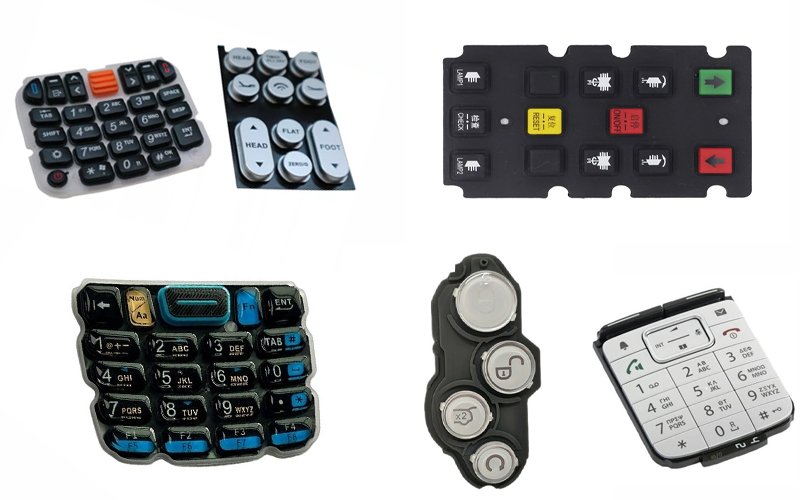
Today the same design concept can be applied to handheld electronics, industrial controllers, access-control equipment, measuring instruments, communication devices, remote controls and other HMI products that need both a rigid visible key and a flexible switch interface.
For industrial or medical equipment, the design requirements usually move beyond appearance. Engineers may need to consider disinfectant resistance, cleaning frequency, ingress protection, glove operation, tactile consistency and long-term bonding reliability.
For automotive or outdoor controls, temperature cycling, UV exposure, chemical contact and long actuation life may become more important.
The material and verification plan should therefore follow the real operating environment of the final product.
When Should You Choose a P+R Keypad?
A P+R keypad makes sense when a product needs a rigid and accurately shaped key surface but still benefits from silicone rubber underneath.
It is particularly useful when designers need better control over keycap appearance, durable legends, illuminated characters or a hard tactile surface.
A conventional silicone rubber keypad remains a better solution when simplicity, sealing, lower tooling cost and fewer assembly operations are the main priorities.
The decision should therefore be made at the HMI architecture stage rather than after the enclosure has already been finalized.
P+R Keypad DFM at Fecision
For a custom P+R keypad project, DFM should consider the plastic keycap, silicone rubber section, switch mechanism, PCB and enclosure as one assembly.
Fecision can support silicone keypad molding, plastic injection molding, tooling development and assembly for custom P+R keypad projects. During DFM, the key stack, dome alignment, bonding geometry, key travel, LED clearance and mounting structure can be reviewed before production tooling is finalized.
Providing the 3D enclosure model, PCB layout, dome specification and target actuation force at the beginning of the project usually makes this process much more efficient.
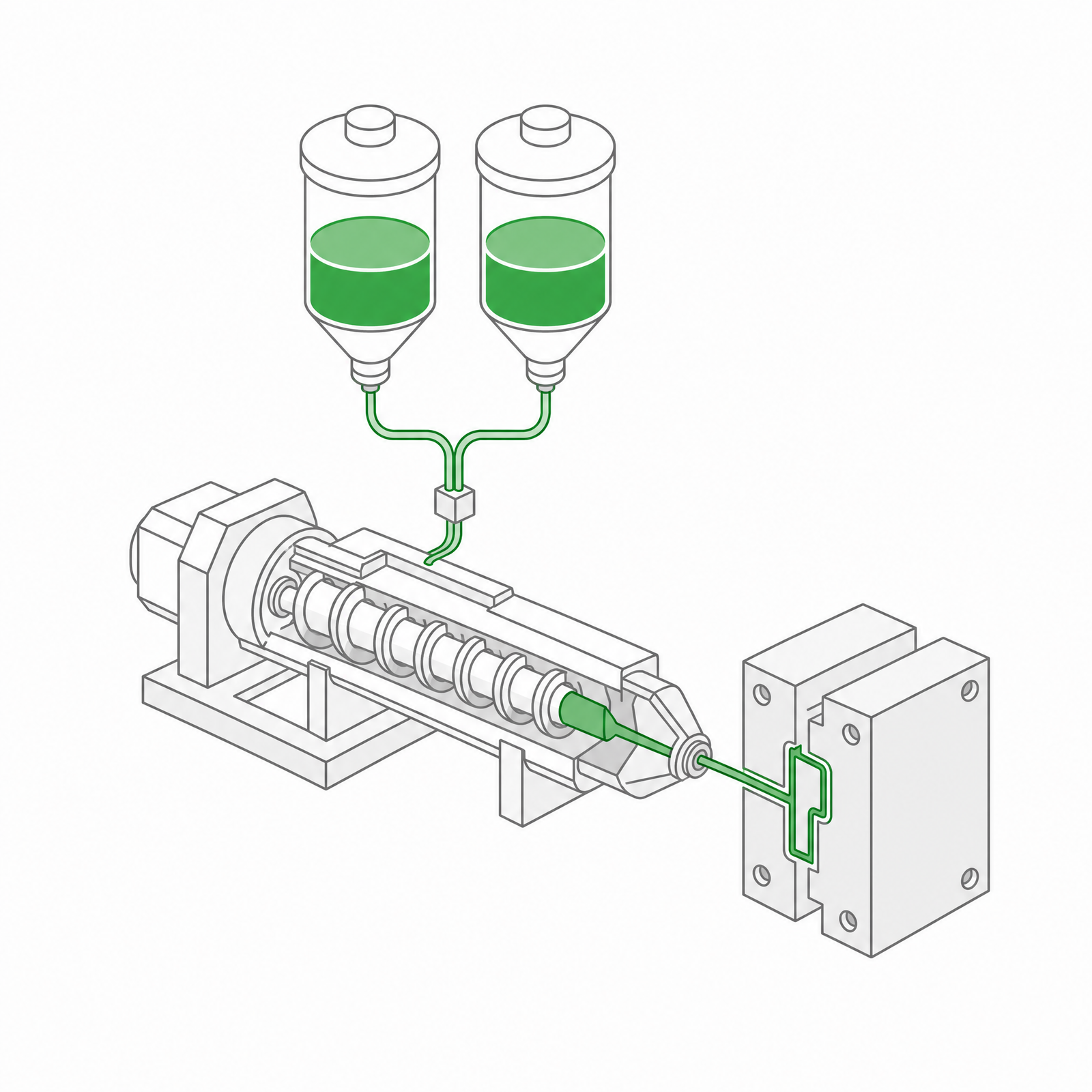 LSR Injection Molding
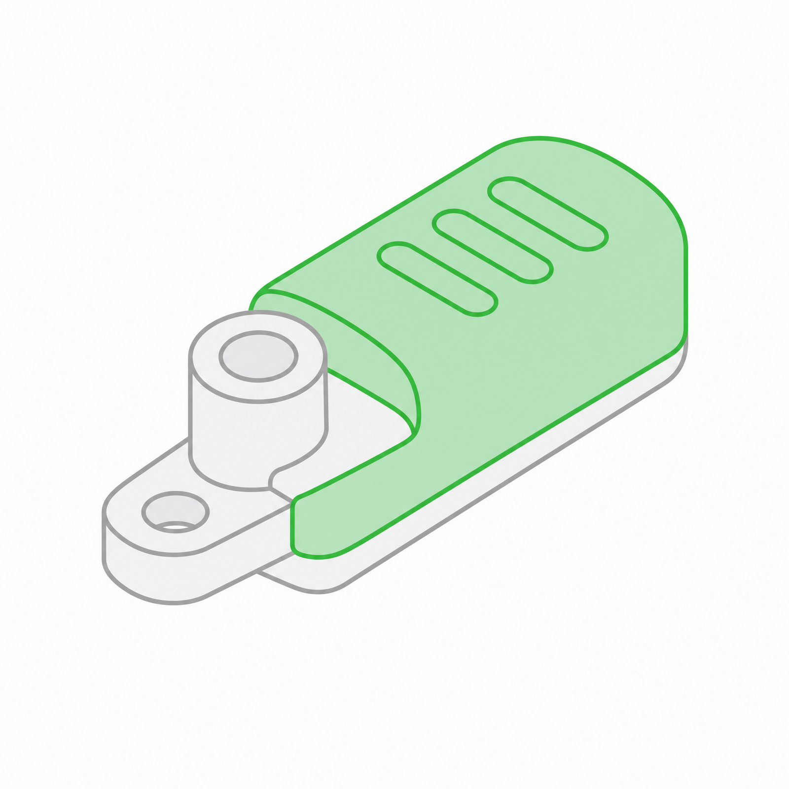 Silicone Rubber Overmolding
 Compression Molding
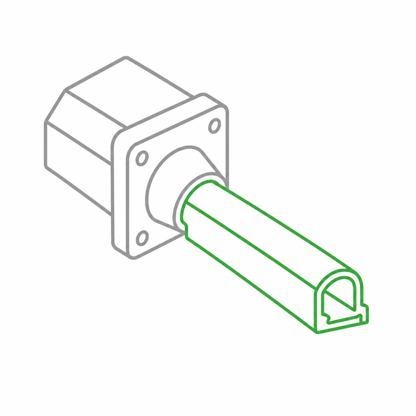 Silicone Rubber Extrusion
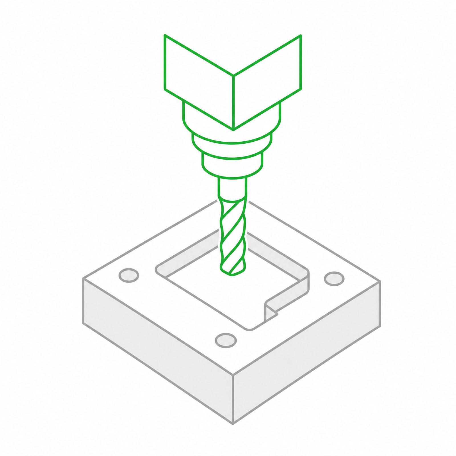 In-house Tooling